- Railroad switch
-
For other uses, see Switch (disambiguation).
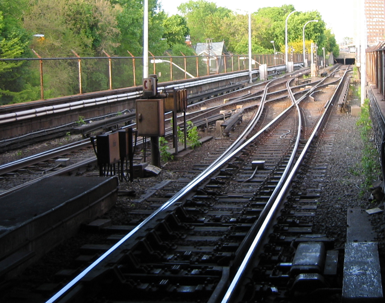
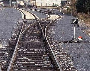 A right-hand railroad switch with point indicator pointing to right
 Animated diagram of a right-hand railroad switch, rail track A divides into two: track B (the straight track) and track C (the diverging track)
- This article primarily uses North American terminology. British and Commonwealth terms are given in parentheses.
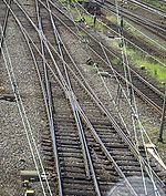
A railroad switch, turnout or [set of] points is a mechanical installation enabling railway trains to be guided from one track to another at a railway junction.
The switch consists of the pair of linked tapering rails, known as points (switch rails or point blades), lying between the diverging outer rails (the stock rails). These points can be moved laterally into one of two positions to direct a train coming from the narrow end toward the straight path or the diverging path. A train moving from the narrow end toward the point blades (i.e. it may go either left or right) is said to be executing a facing-point movement.
Unless the switch is locked, a train coming from either of the converging directs will pass through the points onto the narrow end, regardless of the position of the points, as the vehicle's wheels will force the points to move. Passage through a switch in this direction is known as a trailing-point movement.
A switch generally has a straight "through" track (such as the main-line) and a diverging route. The handedness of the installation is described by the side that the diverging track leaves. Right-hand switches have a diverging path to the right of the straight track, when coming from the narrow end and a left-handed switch has the diverging track leaving to the opposite side.
A straight track is not always present; for example, both tracks may curve, one to the left and one to the right (such as for a Wye Switch) or both tracks may curve, with differing radii, in the same direction.
Operation
 The operation of a railroad switch. In this animation, the red track is the one travelled during a facing-point movement. The switch mechanism, shown in black, may be operated remotely using an electric motor or hand-operated lever or from a nearby ground frame.
A railroad car's wheels are guided along the tracks by coning of the wheels.[1] Only in extreme cases does it rely on the flanges located on the insides of the wheels. When the wheels reach the switch, the wheels are guided along the route determined by which of the two points is connected to the track facing the switch. In the illustration, if the left point is connected, the left wheel will be guided along the rail of that point, and the train will diverge to the right. If the right point is connected, the right wheel's flange will be guided along the rail of that point, and the train will continue along the straight track. Only one of the points may be connected to the facing track at any time; the two points are mechanically locked together to ensure that this is always the case.
A mechanism is provided to move the points from one position to the other (change the points). Historically, this would require a lever to be moved by a human operator, and some switches are still controlled this way. However, most are now operated by a remotely controlled electric motor or by pneumatic or hydraulic actuation.
In a trailing-point movement, the wheels will force the points to the proper position. This is sometimes known as running through the switch. Some switches are designed to be forced to the proper position without damage. Examples include variable switches, spring switches, and weighted switches.
If the points are rigidly connected to the switch control mechanism, the control mechanism's linkages may be bent, requiring repair before the switch is again usable. For this reason, switches are normally set to the proper position before performing a trailing-point movement.[2]
An example of a mechanism that would require repair after a run-through in the trailing direction is a clamp-lock. This mechanism is popular in the UK, but the damage caused is common to most types of switches.
High-speed operation
Generally, switches are designed to be safely traversed at low speed. However, it is possible to modify the simpler types of switch to allow trains to pass at high speed. More complicated switch systems, such as double slips are restricted to low-speed operation. On European High Speed Lines, it is not uncommon to find switches where a speed of 200 km/h (124.3 mph) or more is allowed.[citation needed]
The conventional way to increase turnout speeds is to lengthen the turnout and use a shallower frog angle. If the frog angle is so shallow that a fixed frog cannot support a train's wheels, a swingnose crossing (US: moveable point frog) will be used. Higher speeds are possible without lengthening the turnout by using uniformly curved rail and a very low entry angle.[clarification needed]
An AREMA (American Railway Engineering and Maintenance of Way Association) design number 20 turnout has a diverging speed limit of 45 miles per hour (72.4 km/h).[3][4]
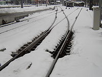
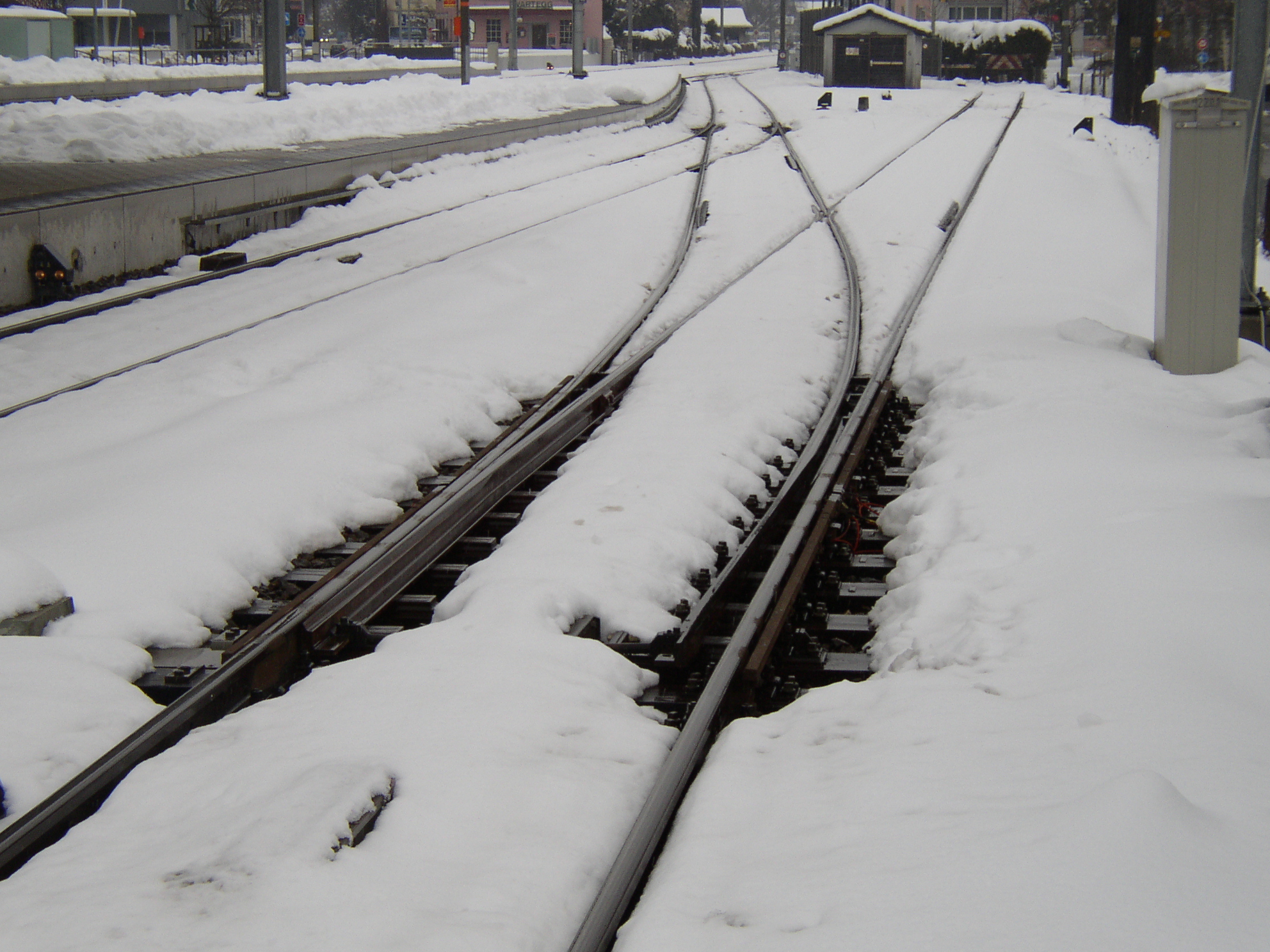
Operation in cold conditions
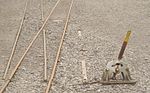
 Gas heating keeps a switch free from snow and ice
In cold conditions, snow and ice can prevent the correct operation of switches. In the past, people were employed by railway companies to keep the switches clear by sweeping the snow away, and this is still used in some countries, especially on minor lines. Some were provided with gas torches for melting ice. More recently, switches have had heaters installed in the vicinity of the points so that the temperature of the rails in these areas can be kept above freezing. The heaters may be powered by gas or electricity. In cases where gas or electric heaters are unable to be used due to logistical or economical constraints anti-icing chemicals can be applied to create a barrier between the metal surfaces of the switch and ice.
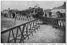 A switch on the Listowel and Ballybunion Railway, Ireland, in 1912
Tram and monorail systems
The switch points of tram lines are often operated remotely by the driver, who intentionally draws power or not when passing under a special short segment of the overhead wire. Alternatively in modern times, radio telemetry or the like is used.
Monorail systems have special switches.
Roller coaster switches
Many roller coasters have switches for the siding, or even for a double station system, for example in Disneyland Resort Paris' Space Mountain and Air at Alton Towers.
Regular rail can cross its own track because the gaps in the rails for wheel flanges are narrow, permitting the bladed design in this article. Round pipe roller coaster rails and box beam monorail rails usually have wheels riding at angles other than on top. These additional other angle wheels are a larger loading gauge, requiring big gaps in the rail (structure gauge) where rails cross or meet.
There are three basic switch designs for roller coasters. Flexing, substituting and table rotating rails have all been used. Flexing the entire rail truss, fixed at one end, to point towards an alternate destination requires manipulating a long segment of rail. Substituting a segment requires placing two or more segments of rail on flat plate that is moved in its entirety to provide straight or curved track.
 Substitution track switch for rail at Chester Zoo
Alternatively these substitution track segments can be wrapped around a rotating cylinder, creating a triangular truss or a two sided plate. Rotating a table with a curved track segment in a Y junction is the less used third option. If the curved track turns the cars 60 degrees, and three rail lines meet as three equally spaced spokes, 120 degrees apart, then the curved track sitting on a turn table can be rotated to connect any two of the three rail lines at this junction, creating a triangle junction.
Classification
The divergence and length of a switch is determined by the angle of the frog (the point in the switch where two rails cross, see below) and the angle or curvature of the switch blades. The length and placement of the other components are determined from this using established formulas and standards. This divergence is measured as the number of units of length for a single unit of separation.
In North America this is generally referred to as a switch's "number". For example, on a "number 12" switch, the rails are one unit apart at a distance of twelve units from the center of the frog. In the United Kingdom points and crossings using chaired bullhead rail would be referred to using a letter and number combination. The letter would define the length (and hence the radius) of the switch blades and the number would define the angle of the crossing (frog). Thus an A7 turnout would be very short and likely only to be found in tight places like dockyards whereas an E12 would be found as a fairly high speed turnout on a mainline.
Safety
The correct setting of points is fundamental to the safe running of a railway. For example, an incorrectly set switch may result in two trains being on the same track, potentially causing a collision.
Perhaps the greatest security challenge in railway operation is preventing the tampering of manually-operable switches. Similar (non-fatal) wrecks near Newport News, Virginia on August 12, 1992 and in Stewiacke, Nova Scotia on April 12, 2001 resulted from switches being thrown open in front of the trains by teenage saboteurs. To prevent these incidents, most unused switches are locked up.
The 1998 Eschede train disaster was one of the world's deadliest high-speed train accidents, resulting in over 100 deaths. It occurred when a wheel rim failed at 200 km/h (125 mph), partially derailing the car. The wheel rim went through the floor of the carriage and was dragging on the ground. On arrival at the junction it threw the switch, causing the rear wheels of the car to switch onto a track parallel to the track taken by the front wheels. The car was thereby thrown into and destroyed the piers supporting a 300-tonne roadway overpass.
In 1980, 18 people died in the Buttevant Rail Disaster at Buttevant, Co. Cork in Ireland, when the Dublin-Cork express was derailed at high speed after being inadvertently switched into a siding via ground frame operated points.
The Potters Bar rail crash at Potters Bar, Hertfordshire in the United Kingdom occurred in May 2002, when a switch sprang to a different position as a coach crossed it, a type of mishap called "splitting the switch." The front wheels of a coach progressed along the straight track as intended, but the rear wheels slewed along the diverging track. This caused the whole coach to detach from the train and slew sideways across the platform ahead. Fortunately, the movement of the switch occurred beneath the final coach, so that although 7 people were killed, the front coaches remained on the tracks. Poor maintenance of the points was found to be the primary cause of the crash.
The initial conclusion of the inquiry into the Grayrigg derailment of February 23, 2007 blames an incorrectly maintained set of points.
History
On early lines, vehicles were moved between tracks by means of sliding rails. The switch as we know it was patented by Charles Fox in 1832.
Prior to the widespread availability of electricity, switches at heavily-traveled junctions were operated from a signal box constructed near the tracks through an elaborate system of rods and levers. The levers were also used to control railway signals to control the movement of trains over the points. Eventually, mechanical systems known as interlockings were introduced to make sure that a signal could only be set to allow a train to proceed over points when it was safe to do so. On some low-traffic branch lines, in self-contained marshalling yards, or on heritage railways, switches may still be operated in this way.
Components
Points (point blades)
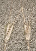
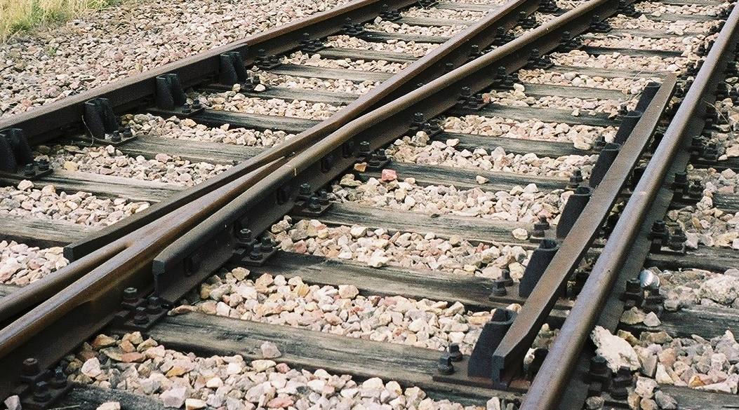
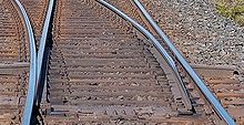 This detail of a switch shows the pair of tapered moveable rails known as the switch points (switch rails or point blades)
The points (switch rails or point blades) are the movable rails which guide the wheels towards either the straight or the diverging track. They are tapered on most switches, but on stub switches they have square ends.
In the UK and Commonwealth countries, the term points refers to the entire mechanism, whereas in North America the term refers only to the movable rails.
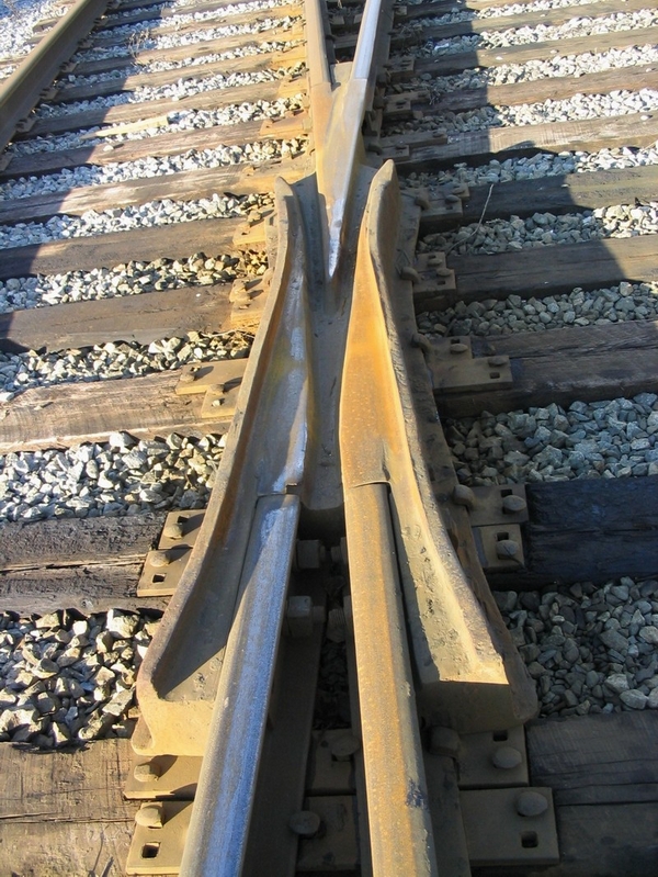
Frog (common crossing)
 A one-piece cast frog. The shiny line crosses the rusty line. This North American "self-guarding cast manganese" frog without guard rails has raised flanges on the frog, bearing on the face of the wheel as it passes through the frog.
The frog, also known as the common crossing (or K-Rail in Australian terminology), refers to the crossing point of two rails. This can be assembled out of several appropriately cut and bent pieces of rail or can be a single casting of manganese steel. On lines with heavy use the casting may be treated with explosive shock hardening to increase service life.[5] A frog forms part of a railroad switch, and is also used in a level junction (flat crossing). The frog is designed to ensure the wheel crosses the gap in the rail without "dropping" into the gap; the wheel and rail profile ensures that the wheel is always supported by at least one rail. To ensure that the wheels follow the appropriate flangeway, a check-rail ("guard rail" North American terminology) is installed inside the rail opposite the frog.[citation needed]
On lines with heavy and/or high-speed traffic, a swingnose crossing (moveable point frog) may be used. As the name implies, there is a second mechanism located at the frog. This moves a small portion of rail, to eliminate the gap in the rail that normally occurs at the frog. A separate switch machine is required to operate the movable point frog switch.
This term "frog" is taken from shape of the device resembling a leaping frog with legs extended forward and to the rear of the body.[citation needed]
On dual-gauge switches, a special frog is used where the 3rd rail crosses the common rail. Denver and Rio Grande crews called this a "toad."
Guard rail (check rail)
 The frog (left) and guard rail (right) of a switch
A guard rail (check rail) is a short piece of rail placed alongside the main (stock) rail opposite the frog. These exist to ensure that the wheels follow the appropriate flangeway through the frog and that the train does not derail. Generally, there are two of these for each frog, one by each outer rail. Guard rails are not required with a "self-guarding cast manganese" frog, as the raised parts of the casting serve the same purpose. These frogs are for low-speed use and are common in rail yards.
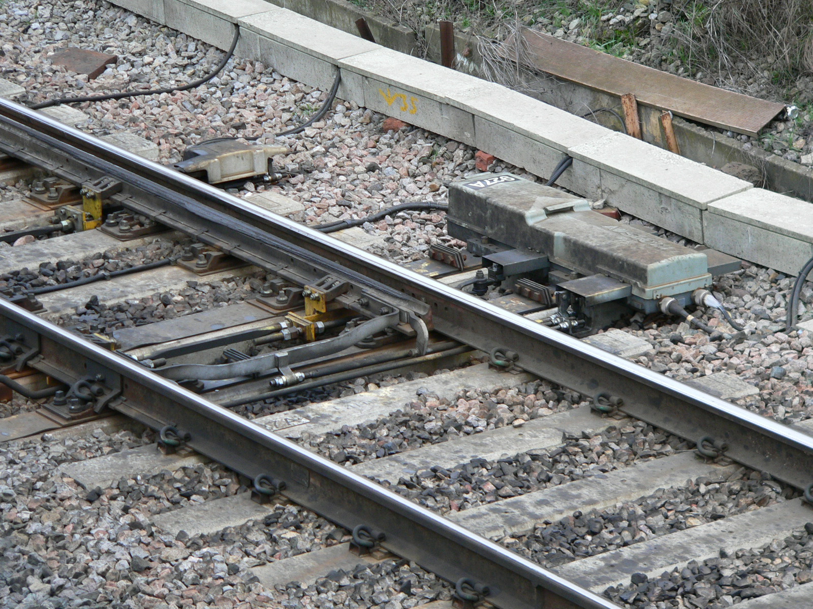
 The switch motor (in this case an electric motor) and associated mechanism used to operate this switch can be seen to the right in the picture
Check rails are often used on really sharp curves, even where there are no switches.[6]
Switch motor
A switch motor (also known as a switch machine, point motor or point machine) is an electric, hydraulic or pneumatic mechanism that aligns the points with one of the possible routes. The switch motor also includes electrical contacts to detect that the switch has completely set and locked. If the switch fails to do this, the governing signal is kept at red (stop). There is also usually some kind of manual handle for operating the switch in emergencies, such as power failures.
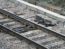
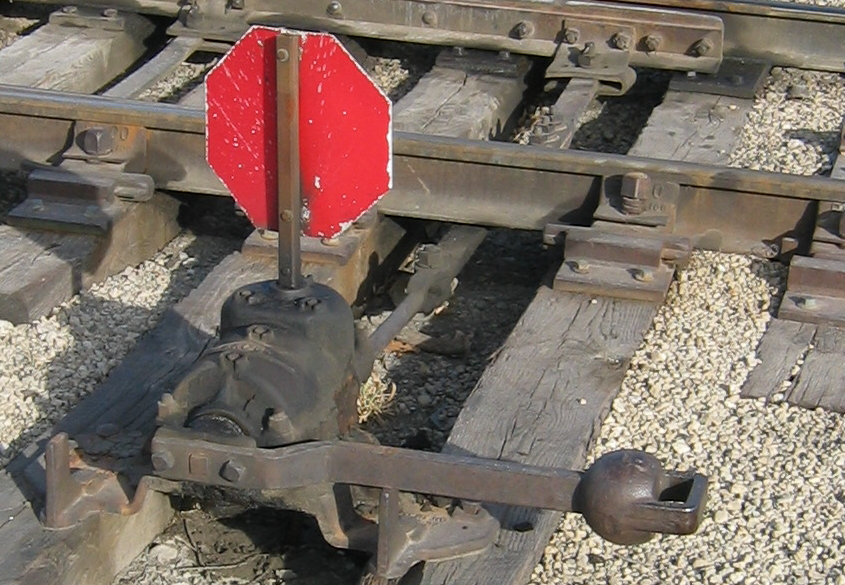
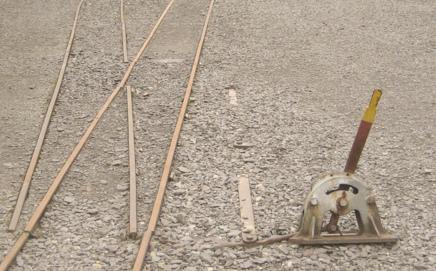
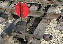 An example of a mechanism used at a switch. The two points are linked together with a throw bar. The throw bar extends to the lever on the near side of the track, which is used to throw the switch. This is an example of a low switch stand, used at locations where there is not sufficient clearance for a tall switch stand. This particular stand is designed to be trailed through by rolling stock, which will cause the points to become lined for the route that the wheels have passed through. It has a reflectorised target.
A patent by W. B. Purvis dates from 1897.
Points lever
A points lever, ground throw, or switchstand is a lever and accompanying linkages that are used to align the points of a switch manually. This lever and its accompanying hardware is usually mounted to a pair of long sleepers that extend from the switch at the points. They are often used in a place of a switch motor on infrequently used switches. In some places, the lever may be some distance from the points, as part of a lever frame or ground frame. To prevent the tampering of switches by outside means, these switches are locked up when not in use.
Point Machine Conversion - Manual to Motorized
A point machine conversion system consist in a remotely controlled device attached to an existing manually-operated point that allows the shunter/driver to remotely operate hand points with a radio handset. Each converter can be used as a stand alone or multiple units can be installed operating together with routing.
Facing point lock
A facing point lock, FPL or point lock is a device which, as the name implies, locks a set of points in position, as well as proving that they are in the correct position. The "facing point" part of the name refers to the fact that they are to prevent movement of the points during facing moves, where a train could potentially split the points (end up going down both tracks) if the points were to move underneath the train - during trailing moves, the wheels of a train will force the points into the correct position if they attempt to move.
In the United Kingdom, FPLs were incredibly common from an early date, due to laws being passed which forced the provision of FPLs for any routes travelled by passenger trains - it was, and still is, illegal for a passenger train to make a facing move over points without them being locked, either by a point lock, or temporarily clamped in one position or another.[7]
Joints
Joints are used where the moving points meet the fixed rails of the switch. They allow the points to hinge easily between their positions. Originally the movable switch blades were connected to the fixed closure rails with loose joints, but since steel rails are somewhat flexible it is possible to make this join by thinning a short section of the rail itself. This can be called a heelless switch.
Straight and curved switches
Turnouts were originally built with straight switch blades, which ended at the pointed end with a sharp angle. These switches cause a bump when the train traverses in the turnout direction. The switch blades could be made with a curved point which meets the stockrail at a tangent, causing less of a bump, but the disadvantage is that the metal at the point is thin and necessarily weak. A solution to these conflicting requirements was found in the 1920s on the German Reichsbahn. The first step was to have different rail profile for the stock rails and switch rails, with the switch rails being about 25 mm (0.98 in) less high, and stockier in the middle.
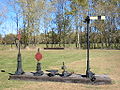
Point indicators
As it is difficult to see the lie of a switch from a distance, especially at night, European railways and their subsidiaries provide point indicators which are often illuminated.
Components gallery
-
A swingnose crossing. The point of the V-shaped rail is moved to align the rail in the appropriate direction where the two rails cross.
-
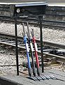
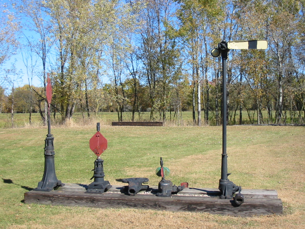
Several different styles of switch stand on display
-
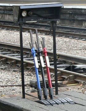
A ground frame (at Bristol Temple Meads station, UK) contains a few levers for manually operating nearby points
blue - release
black - points
red - signal -
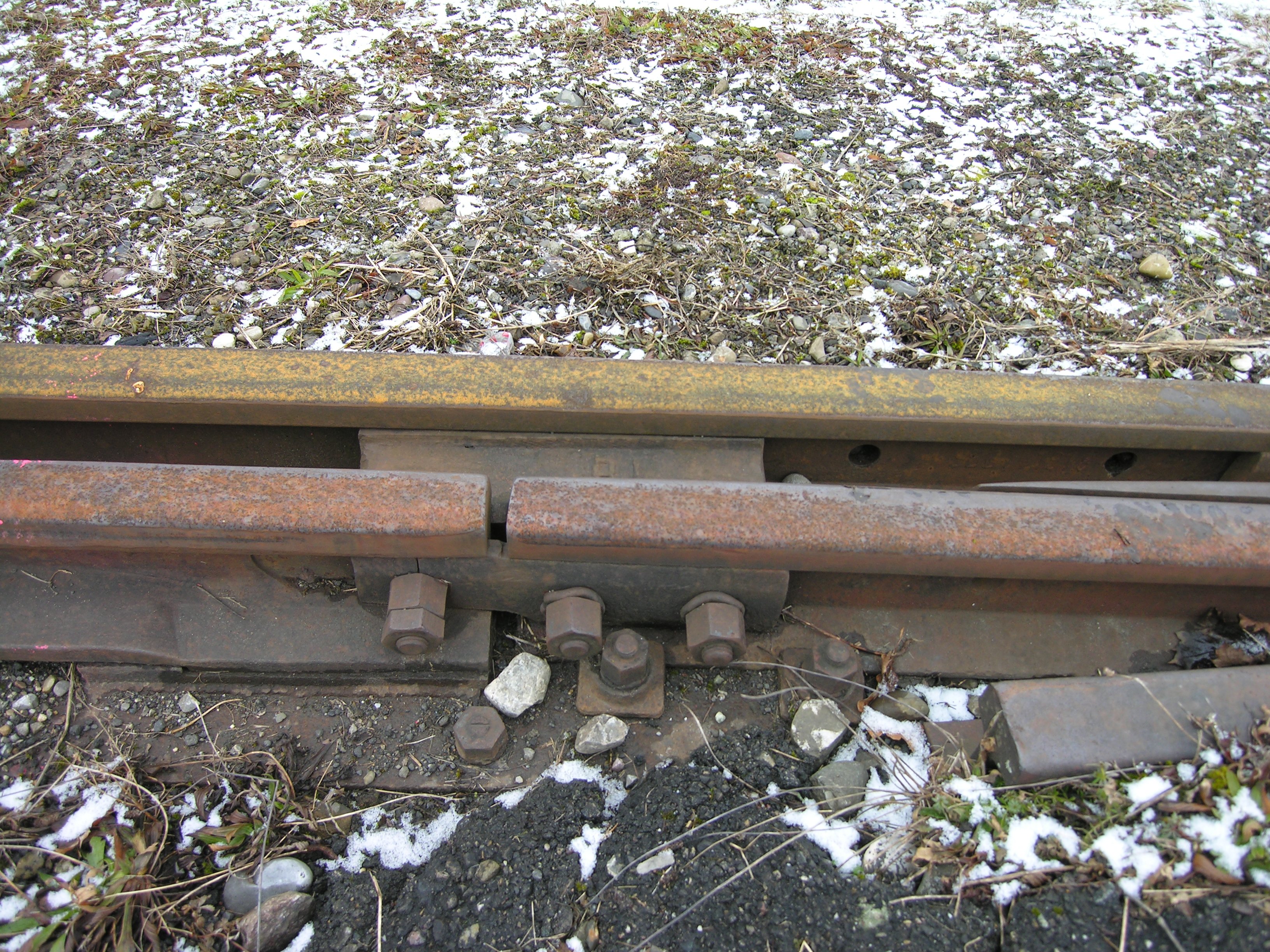
A light industrial or yard track switch joint, where the points are joined to the closure rails by bolts through a "joint bar" or "fish plates"
Types of switches
 A double switch, or double slip. The points are set to connect the upper left and lower right tracks.
Apart from the standard right-hand and left-hand switches, switches commonly come in various combinations of configurations.
Slip switches
Double slip
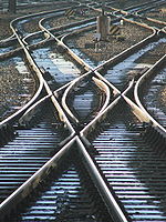
A double slip switch (double slip) is a narrow-angled diagonal flat crossing of two lines combined with four pairs of points in such a way as to allow vehicles to change from one straight track to the other, as well as going straight across. A train approaching the arrangement may leave by either of the two tracks on the opposite side of the crossing. To reach the third possible exit, the train must change tracks on the slip and then reverse.
The arrangement gives the possibility of setting four routes, but because only one route can be traversed at a time, the four blades at each end of the crossing are often connected to move in unison, so the crossing can be worked by just two levers or point motors. This gives the same functionality of two points placed end to end. These compact (albeit complex) switches usually are found only locations where space is limited, such as station throats (i.e., approaches) where a few main lines spread out to reach any of numerous platform tracks.
In North America, the arrangement may also be called a double switch, or more colloquially, a puzzle switch. The Great Western Railway in the United Kingdom used the term double compound points, and the switch is also known as a double compound in Victoria (Australia).
Single slip
A single slip switch works on the same principle as a double slip but provides for only one switching possibility. Trains approaching on one of the two crossing tracks can either continue over the crossing, or switch tracks to the other line. However, trains from the other track can only continue over the crossing, and cannot switch tracks. This is normally used to allow access to sidings and improve safety by avoiding having switch blades facing the usual direction of traffic. To reach the sidings from what would be a facing direction, trains must continue over the crossing, then reverse along the curved route (usually onto the other line of a double track) and can then move forward over the crossing into the siding.
Outside slip
 A double, outside slip in Heidelberg main station
An outside slip switch is similar to the double or single slip switches described above, except that the switch blades are outside of the diamond instead of inside. An advantage over an inside slip switch is that trains can pass the slips with higher speeds. A disadvantage over an inside slip switch is that they are longer and need more space.
An outside slip switch can be so long that its slips do not overlap at all, as in the example pictured. In such a case a single, outside slip switch is the same as two regular switches and a regular crossing. An outside, double slip switch is about the same as a scissors crossover (see below), but with the disadvantages:
- The two parallel tracks cannot be used at the same time;
- That the slips are not straight and thus have a limited speed;
Advantage:
- The crossing can be passed at full speed.
By the disadvantages over both the double inside slip switch and the scissors crossover, double outside slip switches are only used in rare, specific cases.
Crossover
 A scissors crossover: two pairs of switches linking two tracks to each other in both directions
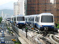 A double crossover on the Wenhu Line of the Taipei Metro system. Trains used to reverse here since the place it located was the original extremity of the line.
A crossover is a pair of switches that connects two parallel rail tracks, allowing a train on one track to cross over to the other. Like the switches themselves, crossovers can be described as either facing or trailing.
When two crossovers are present in opposite directions, one after the other, the four-switch configuration is called a double crossover. If the crossovers overlap it is dubbed a scissors crossover, scissors crossing, or just scissors; or, due to the diamond in the center, a diamond crossover. This makes for a very compact track layout at the expense of using a level junction.
In a setup where each of the two tracks normally carries trains of only one direction, a crossover can be used either to detour "wrong-rail" around an obstruction or to reverse direction. A crossover can also join two tracks of the same direction, possibly a pair of local and express tracks, and allow trains to switch from one to the other.
On a crowded system, routine use of crossovers (or switches in general) will reduce throughput, as the switches must be changed for each train. For this reason, on some high-capacity rapid transit systems, crossovers between local and express tracks are not used during normal rush hour service, and service patterns are planned around use of the usually flying junctions at each end of the local-express line.
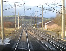 Überleitstelle (crossover) at Richthof between Kirchheim and Langenschwarz stations on the Hanover–Würzburg high-speed railway
In Germany a crossover is known as an Überleitstelle (abbreviated to: Üst) and is defined as an operating control point on the open line.[8] It is also a block section. At an Überleitstelle trains can transfer from one track of a single or double track section of route to another track on a double track section on the same route. Depending on the safety equipment provided, trains may run this other track either by exception or routinely against the normal direction of traffic.
An Überleitstelle must have at least one turnout. On double tracked routes, single and double crossovers are common, each one consisting of two turnouts and an intermediate section. Very often - but not mandatory - the turnouts and block signals at an Überleitstelle are remotely controlled or set from a central signal box.
The official categorisation of an Überleitstelle as a type of junction first arose in Germany with the construction of high-speed railways. Previous to that there were already operating control points at which trains could just transfer from one track to another on the same route, but they were considered as junctions (Abzweigstelle). The latter are still used to refer to those places in stations which enable trains to cross from one route to another.
Stub switch
 A narrow gauge stub switch
A stub switch lacks the tapered points (point blades) of a typical switch. Instead, both the movable rails and the ends of the rails of the diverging routes have their ends cut off square. The switch mechanism aligns the movable rails with the rails of one of the diverging routes. In 19th century US railroad use, the stub switch was typically used in conjunction with a harp switch stand.
The rails leading up to a stub switch are not secured to the sleepers for several feet, and rail alignment across the gap is not positively enforced. Stub switches also require some flexibility in the rails, or an extra joint at which they hinge. Therefore these switches cannot be traversed at high speed or by heavy traffic and so are not suitable for main line use. A further disadvantage is that a stub switch being approached from the diverging route that is not connected by the points would result in a derailment. Yet another disadvantage is that in very hot weather, expansion of the steel in the rails can cause the movable rails to stick to the stock rails, making switching impossible until the rails have cooled and contracted.
Stub switches were more common in the very early days of railways and their tramway predecessors. Now, because of their disadvantages, stub switches are used primarily on narrow gauge lines and branch lines. Some modern monorail switches use the same principle.
Plate switch
 A narrow gauge plate switch
A plate switch incorporates the tapered points of a typical switch into a self-contained plate. Each point blade is moved separately by hand. Plate switches are only used for double-flanged wheels, with wheels running through the plates on their flanges, guided by the edges of the plate and the moveable blade.
Because plate switches can only be used by double-flanged wheels and at extremely low speeds, they are typically only found on hand-worked narrow gauge lines.
Three-way switch
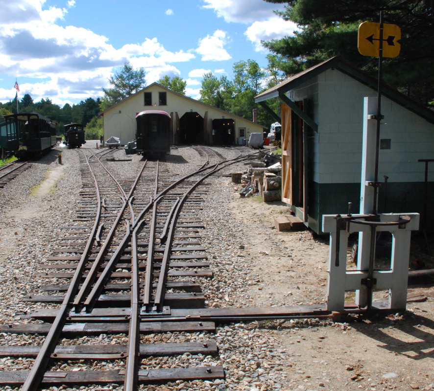
 A three-way stub switch at Sheepscot station on the Wiscasset, Waterville and Farmington Railway
A three-way switch is used to split a railroad track into three divergent paths rather than the more usual two. The complexity of such arrangements usually results in severe speed restrictions, and therefore three-way switches are usually only used in a station or depot where space is restricted and low speeds are normal.
Stub switches can more readily select between three routes, so most three-way switches are stub switches, although some were built using points.[9] It was extremely difficult to hold the two rails the correct distance apart for the length of the switch with these types of switch.
 A three-way switch formerly at Brisbane's Light Street tram depot now on display at the Brisbane Tramway Museum
A three-way switch from a Brisbane tram depot is shown on the right. This example has two points (point blades) on each track, allowing for three diverging routes. The points can both be set to one side, resulting in a vehicle turning off the straight track. Alternatively, the two blades can be separated if the vehicle must continue along the straight track.
Interlaced turnout
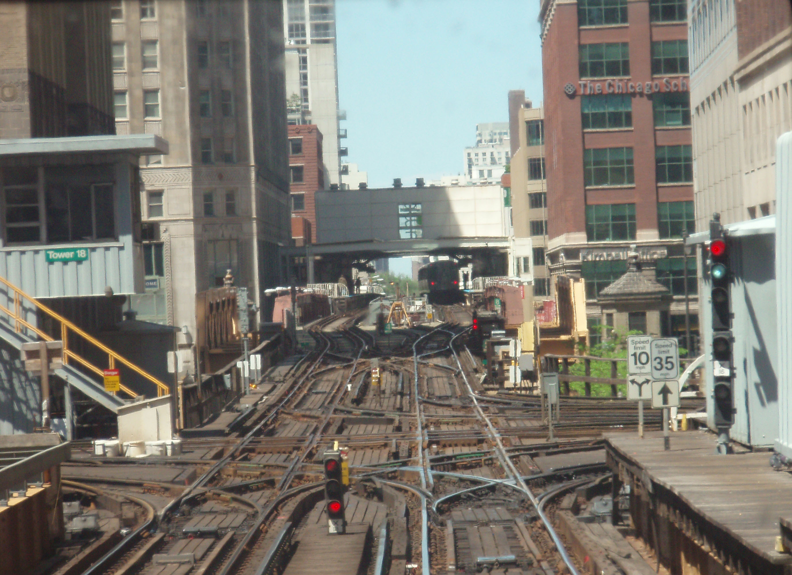
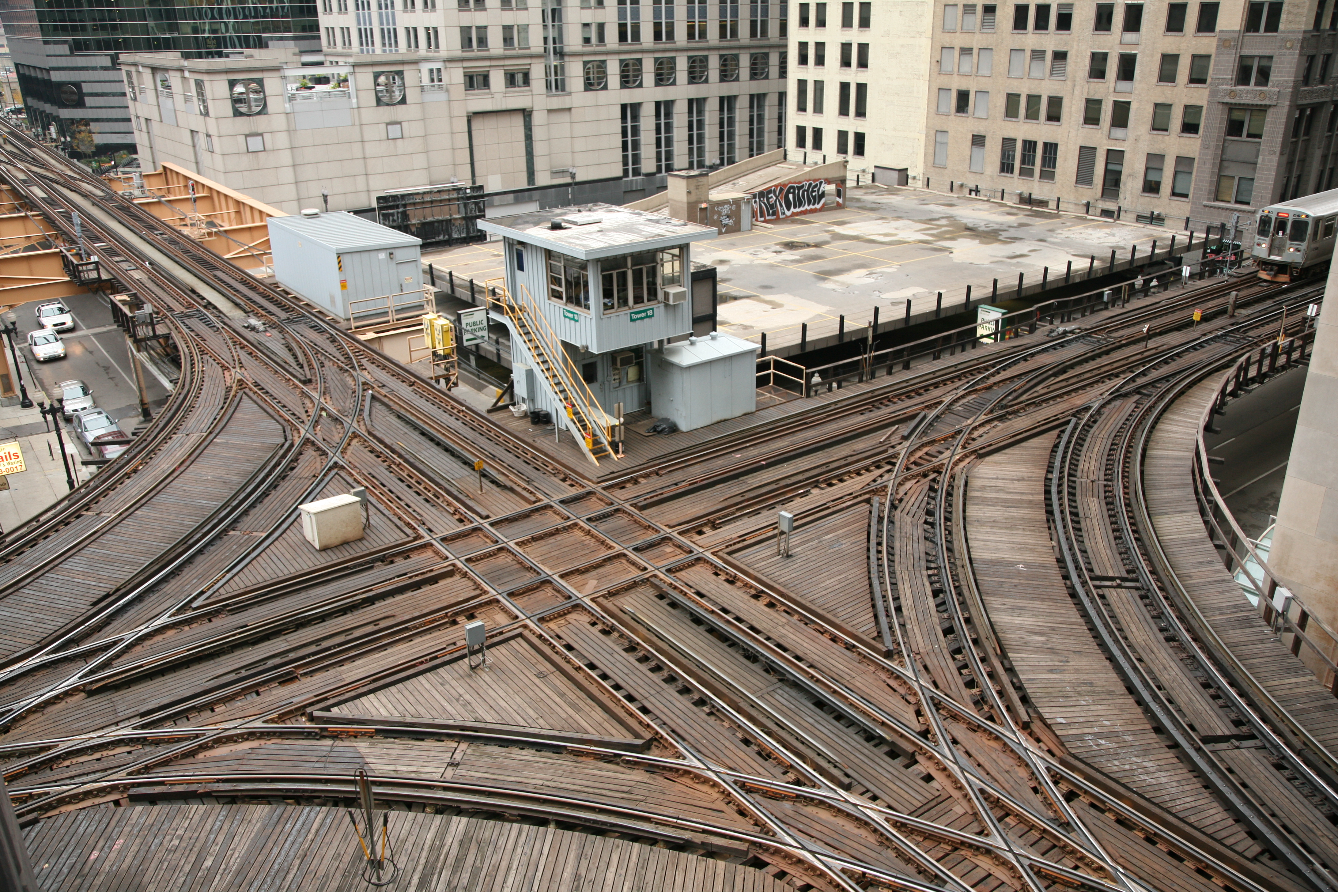
Chicago Transit Authority control tower 18 interlaced turnout

 Interlaced turnouts on the elevated Chicago 'L' north and southbound Purple and Brown lines intersecting with east and westbound Pink and Green lines and the looping Orange line above the Wells and Lake street intersection in the loop.
An interlaced turnout is a different method of splitting a track into three divergent paths. It is an arrangement of two standard turnouts, one left- and one right-handed, in an "interlaced" fashion. The points of the second turnout are positioned between the points and the frog of the first turnout. In common with other forms of three way turnouts an additional common-crossing is required. Due to the inherent complexity of the arrangement, interlaced turnouts are normally only used in locations where space is exceptionally tight, such as station throats or industrial areas within large cities. Interlaced turnouts can also be found in some yards, where a series of switches branching off to the same side are placed so close together that the points of one switch are placed before the frog of the preceding switch.[10]
Wye switch
 A wye switch
A wye switch (Y points) has trailing ends which diverge symmetrically and in opposite directions. The name originates from the similarity of their shape to that of the letter Y. Wye switches are usually used where space is at a premium. In North America this is also called an "Equilateral Switch" or "Equilateral Turnout".Common switches are more often associated with mainline speeds, whereas wye switches are generally low-speed yard switches.
Run-off points
Main article: Catch points Trap points at the exit from a yard
Run-off points are used to protect main lines from stray or runaway railroad cars or from trains passing signals set at danger. In these cases, vehicles would otherwise roll onto and obstruct a main line (sometimes known as fouling) and cause an accident. Depending on the situation in which they are used, run-off points are referred to either as trap points or catch points. Derailers are another device used for the same purpose.
Catch points are installed on the running line itself, where the railway climbs at a steep gradient. They are used to prevent runaway vehicles colliding with another train further down the slope. In some cases, catch points lead into a sand drag to safely stop the runaway vehicle, which may be travelling at some speed. Catch points are usually held in the 'derail' position by a spring. They can be set to allow a train to pass safely in the downhill direction using a lever or other mechanism to override the spring for a short time.
Catch points originate from the days of the 'unfitted' goods train. These trains did not have a mechanism in place to automatically brake runaway cars. Catch points were therefore required to stop the rear portion of a train that had become divided, although they would also stop vehicles that had run away for any other reason. Now that trains are all 'fitted', catch points are mostly obsolete.
Similar to catch points, trap points are provided at the exit from a siding or where a goods line joins a line that may be used by passenger trains. Unless they have been specifically set to allow traffic to pass onto the main line, the trap points will direct any approaching vehicle away from the main line. This may simply result in the vehicle being derailed, but in some cases a sand drag is used, especially where the vehicle is likely to be a runaway travelling at speed due to a slope.
Derailers
Main article: DerailA derailer works by derailing any vehicle passing over it. There are different types of derailer, but in some cases they consist of a single switch point installed in a track. The point can be pulled into a position to derail any equipment that is not supposed to pass.
Dual gauge switches
 A dual gauge switch in Japan
Dual gauge switches are used in dual gauge systems. There are various possible scenarios involving the routes that trains on each gauge may take, including the two gauges separating or one gauge being able to choose between diverging paths and the other not. Because of the extra track involved, dual gauge switches have more points and frogs than their single gauge counterparts. This limits speeds even more than usual.
A related formation is the 'swish' or rail exchange, where (usually) the common rail changes sides. These have no moving parts, the narrower gauge wheels being guided by guard rails as they transition from one rail to another. The wider gauge only encounters continuous rail so is unaffected by the exchange. At dual gauge turntables, a similar arrangement is used to move the narrow gauge track from one side to a central position.
Rack railway switches

Rack railway switches are as varied as rack railway technologies. Where use of the rack is optional, as on the Zentralbahn in Switzerland or the West Coast Wilderness Railway in Tasmania, it is common to place turnouts only in relatively flat areas where the rack is not needed. On systems where only the pinion is driven and the conventional rail wheels are idlers, such as the Dolderbahn in Zurich, Štrbské Pleso in Slovakia and the Schynige Platte rack railway, the rack must be continuous through the switch. The Dolderbahn switch works by bending all three rails, an operation that is performed every trip as the two trains pass in the middle. The Štrbské Pleso and Schynige Platte Strub rack system instead relies on a complex set of moving points which assemble the rack in the traversed direction and simultaneously clear the crossed direction conventional rails. In some rack systems, such as the Morgan system, where locomotives always have multiple driving pinions, it is possible to simplify turnouts by interrupting the rack rail, so long as the interruption is shorter than the spacing between the drive pinions on the locomotives.[11]
Switch diamond
 A switch diamond at a junction in the UK
Although not strictly speaking a turnout, a switch diamond is an active trackwork assembly used where the crossing angle between two tracks is too shallow for totally passive trackwork- the unguided sections of each rail would overlap. These vaguely resemble two standard points assembled very closely toe-to-toe. These would also often utilise swingnose crossings at the outer ends to ensure complete wheel support in the same way as provided on shallow angle turnouts. In North America these are known as Movable-Point Diamonds. In the UK, where the angle of divergence is shallower than 1 in 8 (centre-line measure) a switched diamond will be found rather than a passive or fixed diamond.
Such switches are usually implemented on the basis of increasing the safe crossing speed. Open blades impose a speed restriction due to the potential of the crossing impact fracturing the rail. Remember that both wheels on an axle hit the crossing gaps almost simultaneously. Switching the blades like the photo shows allows a much higher speed across the gap.
The frog end is not as bad, because the outer rail is still continuous, the wing rail (the bit that bends away after the frog gap) provides a gradual transition, and the check rail avoids the possibility of points splitting. Note how the wing rail has a wider shiny section, showing how the wheel load is transferred across the gap.
Single-point switch
 A single-point switch on the Toronto streetcar system
Single point switches, known as Tongue and Plain Mate switches, are sometimes used on freight railways in slow speed operation in paved areas such as in ports. In the United States, they are regulated by provision 213.135(i) of the Federal Railroad Administration Track Safety Standards. On streetcar (tram) systems using grooved rails, if the wheels on both sides of the car are connected by a solid axle, only one switchpoint is needed to steer it onto one or the other track. The opposite wheel is supported for a short distance by its flange running in the groove.
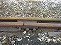
Expansion joint
Expansion joints are a construction that allows the rails to move relative to each other due to changes in temperature while retaining continuity for through traffic.[12] They are often used on large bridges such as the Sydney Harbour Bridge.
Turnout speeds
Turnout speeds are governed by a number of factors.
As a general rule, the finer the crossing angle of a turnout, the higher the turnout speed. In USA, turnouts are rated by number, which represents the ratio of divergence per length as measured at the frog. A rule of thumb is that the rated speed of a switch is twice the number.
- #10 - 15 mph (24 km/h)
- #15 - 30 mph (48 km/h)
- #20 - 40 mph (64 km/h)
In Russia and CIS switches a marked with tangent of crossing angle:
- 1/6 - sorting yards only, whenever it is impossible to install a better switch
- 1/9 - 40 km/h (25 mph), the most common switch, installed by default.
- 1/11 - 50 km/h (31 mph), used where passenger trains follow a diverging path. Swingnose crossing may be installed if required.
- 1/18 - 80 km/h (50 mph), used where either non-interruptible movement is required or the mainline derives from the branch line.
- 1/22 - 120 km/h (75 mph), rarely used, hi-speed lines only.
Other considerations include the type of turnout (e.g. normal or swing nose, or slips etc.), wear and tear issues, and the weight and type of the vehicle passing over. Speeds for a trailing movement may be higher than for a facing movement. In many systems, speed limits vary depending on the type of train - for example, a turnout can have a "normal" speed limit for locomotive hauled trains, and a higher speed for multiple unit or high speed trains.
Turnouts with curved or tangential switch blades have higher speed than old style turnouts with straight switch blades.
See also
- Centralized traffic control
- Double junction
- Expedition Everest, roller coaster with switches
- Minimum railway curve radius
- Rail terminology (US/UK differences highlighted)
References
- ^ http://www.youtube.com/watch?v=y7h4OtFDnYE Physicist Richard Feynman explains how a train stays on the tracks. BBC TV 'Fun to Imagine' (1983)
- ^ Rules 8.9, 8.15, and 8.18, General Code of Operating Rules, Fifth Edition. (c) 2005 General Code of Operating Rules Committee.
- ^ Increasing speed through turnouts, from FindArticles.
- ^ A higher speed turnout, from Federal Railroad Administration, US Department of Transportation.
- ^ Meyers, Marc A. (1994). Dynamic behavior of materials. New York: John Wiley. pp. 5; 570. ISBN 9780471582625.
- ^ "SCENE OF THE ACCIDENT.". The Argus (Melbourne, Vic. : 1848–1956) (Melbourne, Vic.: National Library of Australia): p. 7. 29 January 1906. http://nla.gov.au/nla.news-article10038956. Retrieved 20 July 2011.
- ^ Requirements in regard to the Opening of Railways (1892), from the British Board of Trade
- ^ § 4, paragraph 6 of the Eisenbahn- Bau- und Betriebsordnung or EBO (German Railway Regulations).
- ^ Stub switches
- ^ Example
- ^ John H. Morgan, Switching or Crossover Device for Traction Rack Rail Systems, U.S. Patent 772,736, Oct. 18, 1904.
- ^ http://www.tokyu-car.co.jp/eng/rs/turnout.html
External links
- PowerPoint presentation from Delft University of Technology[dead link]
- J. B. Calvert on Turnouts and the Wharton switch in particular
- MacPherson switch
- ThyssenKrupp handbook
- Pointworks industry and Research departments
- A video explaining how frogs work without resting on the flange
- templot Turnout design
Railway infrastructure Permanent way Permanent way (history) • Permanent way (current) • Railroad tie/Sleeper • Rail fastening system • Track ballast • Rail profile • Fishplate • Breather switch • Datenail • Axe ties • Ladder track • Baulk road • Cant • Minimum radius • Track transition curveTrackwork and track structures Junction • Wye • Railroad switch • Gauntlet track • Railway electrification system • Overhead lines • Track gauge • Railway turntable • Water crane • Track pan • Rail track • Tramway track • Classification yard • Rail yard • Siding • Passing loop • Balloon loopSignalling and safety Railway signalling • Signalling control • Railway signal • Interlocking • Level crossing • Buffer stop • Catch points • Loading gauge • Structure gauge • Block postBuildings Railway track layouts Running lines Rail sidings Junctions Flying junction • Level junction • Double junction • Facing and trailing • Grand union • Wye • Switch / turnout / points • Swingnose crossing • Level crossingStations Side platform • Island platform • Bay platform • Split platform • Terminal station • Balloon loop • Spanish solution • Cross-platform interchange • Interchange stationHillclimbing Categories:- Railway track layouts
- Rail technologies
- Rail infrastructure
- Rail junction types
- Switches


Wikimedia Foundation. 2010.