- Microchannel plate detector
-
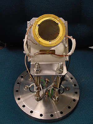 Microchannel plate detector from the Daresbury Recoil Separator
A micro-channel plate (MCP) is a planar component used for detection of particles (electrons or ions) and impinging radiation (ultraviolet radiation and X-rays). It is closely related to an electron multiplier, as both intensify single particles or photons by the multiplication of electrons via secondary emission.[1] However, because a microchannel plate detector has many separate channels, it can additionally provide spatial resolution.
Contents
Basic design
A micro-channel plate is a slab made from highly resistive material of typically 2 mm thickness with a regular array of tiny tubes or slots (microchannels) leading from one face to the opposite, densely distributed over the whole surface. The microchannels are typically approximately 10 micrometers in diameter (6 micrometer in high resolution MCPs) and spaced apart by approximately 15 micrometers; they are parallel to each other and often enter the plate at a small angle to the surface (~8° from normal).
Operating mode
Each microchannel is a continuous-dynode electron multiplier, in which the multiplication takes place under the presence of a strong electric field. A particle or photon that enters one of the channels through a small orifice is guaranteed to hit the wall of the channel due to the channel being at an angle to the plate and thus the angle of impact. The impact starts a cascade of electrons that propagates through the channel, which amplifies the original signal by several orders of magnitude depending on the electric field strength and the geometry of the micro-channel plate. After the cascade, the microchannel takes time to recover (or recharge) before it can detect another signal.
The electrons exit the channels on the opposite side where they are themselves detected by additional means, often simply a single metal anode measuring total current. In some applications each channel is monitored independently to produce an image. Phosphors in combination with photomultiplier tubes have also been used.
Chevron MCP
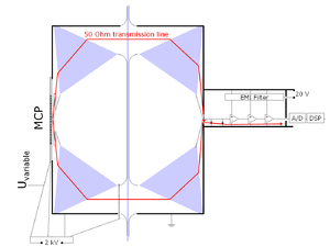
 Dual microchannel plate detector schematic
Most modern MCP detectors consist of two microchannel plates with angled channels rotated 90° from each other producing a chevron (v-like) shape. The angle between the channels reduces ion feedback in the device. In a chevron MCP the electrons that exit the first plate start the cascade in the next plate. The advantage of the chevron MCP over the straight channel MCP is significantly more gain at a given voltage. The two MCPs can either be pressed together or have a small gap between them to spread the charge across multiple channels.
Z stack MCP
This is an assembly of three microchannel plates with channels aligned in a Z shape. Single MCPs can have gain up to 10,000 but this system can provide gain more than 10 million.
The detector
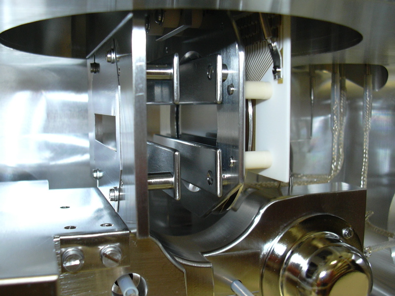
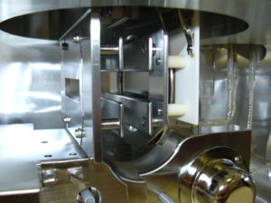 A microchannel plate within a Finnigan MAT 900 sector mass spectrometer position-and-time-resolved-ion-counting (PATRIC) scanning array detector
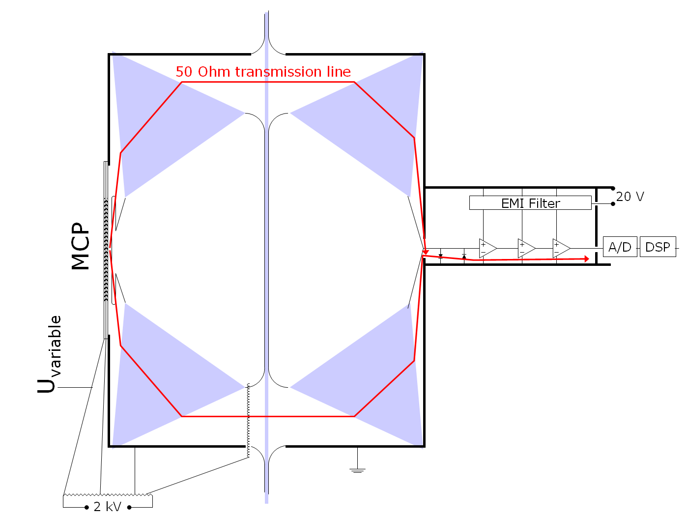
An external voltage divider is used to apply 100 volts to the acceleration optics (for electron detection), each MCP, the gap between the MCPs, and the backside of the last MCP and the collector (anode). The last voltage dictates the time of flight of the electrons and in this way the pulse-width. The anode is a 0.4 mm thick plate with an edge of 0.2 mm radius to avoid high field strengths. It is just large enough to cover the active area of the MCP, because the backside of the last MCP and the anode act as a capacitor with 2 mm separation and large capacitance slows down the signal. The positive charge in the MCP influences positive charge in the backside metalization. A hollow torus conducts this around the edge of the anode plate. A torus is the optimum compromise between low capacitance and short path and for similar reasons usually no dielectric (Markor) is placed into this region. After a 90° turn of the torus it is possible to attach a large coaxial waveguide. A taper permits minimizing the radius so that an SMA connector can be used. To save space and make the impedance match less critical, the taper is often reduced to a small 45° cone on the backside of the anode plate.
The typical 500 volts between the backside of the last MCP and the anode cannot be fed into the preamplifier. Therefore the inner or the outer conductor needs a DC-block, that is, a capacitor. Often it is chosen to only have 10-fold capacitance compared to the MCP-anode capacitance and is implemented as a plate capacitor. Rounded, electro-polished metal plates and the ultra high vacuum allow very high field strengths and high capacitance without a dielectric. The bias for the center conductor is applied via resistors hanging through the waveguide (see bias tee). If the DC block is used in the outer conductor, it is in parallel with the larger capacitor in the power supply. Assuming good screening, the only noise is due to current noise from the linear power regulator. Because the current is low in this application and space for large capacitors is available, and because the DC-block capacitor is fast, it is possible to have very low voltage noise, so that even weak MCP signals can be detected. Sometimes the preamplifier is on a potential (off ground) and gets its power through a low-power isolation transformer and outputs its signal optically.
 Fast MCP electronics featuring a high voltage UHV capacitor (the grey line from bottom to top))
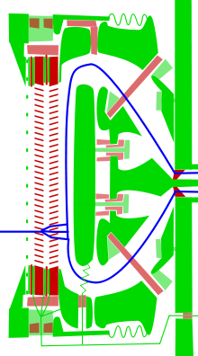 Almost as fast MCP electronics featuring a high voltage UHV capacitor and minimum ceramic
The gain of a MCP is very noisy, especially for single particles. With two thick MCPs (>1 mm) and small channels (< 10 µm), saturation occurs, especially at the ends of the channels after many electron multiplications have taken place. The last stages of the following semiconductor amplifier chain also go into saturation. A pulse of varying length, but stable height and a low jitter leading edge is sent to the time to digital converter. The jitter can be further reduced by means of a constant fraction discriminator. That means that MCP and the preamplifier are used in the linear region (space charge negligible) and the pulse shape is assumed to be due to an impulse response with variable height but fixed shape from a single particle.
Because MCPs have a fixed charge that they can amplify in their life, especially the second MCP has a lifetime problem.[citation needed] It is important to use thin MCPs, low voltage and instead more sensitive and fast semiconductor amplifiers after the anode.[citation needed] (see: Secondary emission#Special amplifying tubes, [1], [2], .[2]).
With high count rates or slow detectors (MCPs with phosphor screen or discrete photomultipliers) pulses overlap. In this case a high impedance (slow, but less noisy) amplifier and an ADC is used. Since the output signal from the MCP is generally small, the presence of the thermal noise limits the measurement of the time structure of MCP signal. However with the fast amplification schemes, is possible to have valuable information on the signal amplitude, even at very low signal values. But yet, not successful on the time structure information of the wideband signals.
Delay line detector
In a delay line detector the electrons are accelerated to 500 eV between the back of the last MCP and a grid. Then they fly for 5 mm and are dispersed over an area of 2 mm. A grid follows. Each element has a diameter of 1 mm and consists of an electrostatic lens focusing arriving electrons through a 30 µm hole of a grounded sheet of aluminium. Behind that a cylinder of the same size follows. The electron cloud induces a 300 ps negative pulse when entering the cylinder and a positive when leaving. After that another sheet, a second cylinder follows, and a last sheet follows. Effectively the cylinders are fused into the center-conductor of a stripline. The sheets minimize cross talk between the layers and adjacent lines in the same layer, which would lead to signal dispersion and ringing. These striplines meander across the anode to connect all cylinders, to offer each cylinder 50 Ω impedance, and to generate a position dependent delay. Because the turns in the stripline adversely affect the signal quality their number is limited and for higher resolutions multiple independent striplines are needed. At both ends the meanders are connected to detector electronics. These electronics convert the measured delays into X- (first layer) and Y-coordinates (second layer). Sometimes a hexagonal grid and 3 coordinates are used. This redundancy reduces the dead space-time by reducing the maximum travel distance and thus the maximum delay, allowing for faster measurements. The microchannel plate detector must not operate over around 60 degree Celcius, otherwise it will degrade rapidly, bakeout without voltage has no influence.[citation needed]
Examples of use
- A 1 GHz real-time display CRT for an analog oscilloscope (the Tektronix 7104) used a microchannel plate placed behind the phosphor screen to intensify the image. Without the plate, the image would be excessively dim, because of the electron-optical design.
- MCP detectors are often employed in instrumentation for physical research, and they can be found in devices such as electron and mass spectrometers.
References
- ^ Wiza, Joseph (1979). "Microchannel plate detectors" (PDF). Nuclear Instruments and Methods 162: 587–601. Bibcode 1979NucIM.162..587L. doi:10.1016/0029-554X(79)90734-1. http://www.burle.com/cgi-bin/byteserver.pl/pdf/tp214.pdf. Retrieved 2007-08-14.
- ^ K.Oba, S.Matsuura (1985). "Characteristics of the newly developed MCP and its assembly". IEEE Ttrans. 32: 350. doi:10.1109/TNS.1985.4336854
Bibliography
- Westmacott G, Frank M, Labov SE, Benner WH (2000). "Using a superconducting tunnel junction detector to measure the secondary electron emission efficiency for a microchannel plate detector bombarded by large molecular ions". Rapid Communications in Mass Spectrometry 14 (19): 1854–1861. doi:10.1002/1097-0231(20001015)14:19<1854::AID-RCM102>3.0.CO;2-M. PMID 11006596.
- Gaire B, Sayler AM, Wang PQ et al. (2007). "Determining the absolute efficiency of a delay line microchannel-plate detector using molecular dissociation". Review of Scientific Instruments 78 (2): 024503. Bibcode 2007RScI...78b4503G. doi:10.1063/1.2671497. PMID 17578132.
- Richards P, Lees J (2002). "Functional proteomics using microchannel plate detectors". Proteomics 2 (3): 256–61. doi:10.1002/1615-9861(200203)2:3<256::AID-PROT256>3.0.CO;2-K. PMID 11921441.
See also
- Particle detector
- Photodetector
- Night vision device
- Image intensifier
- Nanochannel glass materials
External links
Mass spectrometry Mass • m/z • Mass spectrum • MS software • Acronyms Ion source Mass analyzer Detector MS combination Fragmentation Categories:- Mass spectrometry
- Spectrometers
- Image sensors
- Laboratory equipment
- Physical chemistry


Wikimedia Foundation. 2010.