- Newcomen steam engine
-
 Animation of a schematic Newcomen steam engine.
– Steam is shown pink and water is blue.
– Valves move from open (green) to closed (red)The atmospheric engine invented by Thomas Newcomen in 1712, today referred to as a Newcomen steam engine (or simply Newcomen engine), was the first practical device to harness the power of steam to produce mechanical work.[1] Newcomen engines were used throughout Britain and Europe, principally to pump water out of mines, starting in the early 18th century. James Watt's later Watt steam engine was an improved version of the Newcomen engine. For this, Watt is more well known in association with the origin of the steam engine today.
Contents
Precursors
Prior to Newcomen a number of small steam devices of various sorts had been made, but most were essentially novelties.[2] Around 1600 a number of experimenters used steam to power small fountains working something on the principle of a coffee percolator. First a container was filled with water, then heated to make it boil; the steam generated displaced the water, forcing it up a pipe that reached down to the bottom of the water so that it spurted out of a nozzle on top of the container. However, these devices would have been limited in their effectiveness and could only serve to demonstrate a principle.
In 1662 Edward Somerset, second Marquess of Worcester, published a book containing several ideas he had been working on.[3] One was for a steam-powered pump to supply water to fountains; the device alternately used a vacuum and steam pressure. Two containers were alternately filled with steam, then sprayed with cold water making the steam condense; this produced a vacuum that would draw water through a pipe up from a well to the container. A fresh charge of steam under pressure then drove the water from the container up another pipe to a higher-level header before being condensed and repeating the cycle. By working the two containers alternately, delivery rate to the header tank could be increased.
Savery's "Miner's Friend"
In 1698 Thomas Savery patented a steam-powered pump he called the Miner's Friend,[4] essentially identical to Somerset's design and almost certainly a direct copy. The process of cooling and creating the vacuum was fairly slow, so Savery later added an external cold water spray to quickly cool the steam.
Savery's invention had no moving parts. Consequently it cannot be strictly regarded as the first steam "engine", since it could not transmit its power to any external device. There were evidently high hopes for the Miner's Friend, which led Parliament to extend the life of the patent by 21 years, so that the 1699 patent would not expire until 1733. Unfortunately, Savery's device proved much less successful than had been hoped.
A problem with Savery's device stemmed from the fact that a vacuum could only raise water to a maximum height of about 30 ft (9 m), to this could be added another 40 ft (12 m), or so, raised by steam pressure. This was insufficient to pump water out of a mine. In Savery's pamphlet, he suggests setting the boiler and containers on a ledge in the mineshaft and even a series of two or more pumps for deeper levels. Obviously these were inconvenient solutions and some sort of mechanical pump working at surface level – one that lifted the water directly instead of "sucking" it up – was desirable. Such pumps were common already, powered by horses, but required a vertical reciprocating drive that Savery's system did not provide.
Denis Papin's experimental steam cylinder and piston
Louis Figuier in his monumental work[5] gives a full quotation of Denis Papin's paper published in 1690 in Acta eruditorum at Leipzig, entitled "Nouvelle méthode pour obtenir à bas prix des forces considérables" (A new method for cheaply obtaining considerable forces). It seems that the idea came to Papin whilst working with Robert Boyle at the Royal Society in London. Papin describes first pouring a small quantity of water into the bottom of a vertical cylinder, inserting a piston on a rod and after first evacuating the air below the piston, placing a fire beneath the cylinder in order to boil the water away and create enough steam pressure to raise the piston to the top end of the cylinder. The piston was then temporarily locked in the upper position by a spring catch engaging a notch in the rod. The fire was then removed, allowing the cylinder to cool, which condensed steam back into water, thus creating a vacuum beneath the piston. To the end of the piston rod was attached a cord passing over two pulleys and a weight hung down from the cord's end. Upon releasing the catch, the piston was sharply drawn down to the bottom of the cylinder by the pressure differential between the atmosphere and the created vacuum; enough force was thus generated to raise a 60 lb (27 kg) weight. Although the engine certainly worked as far as it went, it was devised merely to demonstrate the principle and having got thus far, Papin never developed it further, although in his paper he did write about the potential of boats driven by "firetubes". Instead he allowed himself to be distracted into developing a variant of the Savery engine.
Introduction and spread
It can be said that Thomas Newcomen took forward Papin's experiment and made it workable, although little information exists as to exactly how this came about, apart from reference to his access to Royal Society documents through acquaintance with Robert Hooke. The main problem to which Papin had given no solution was how to make the action repeatable at regular intervals. The way forward was to provide as Savery had done, a boiler capable of assuring a continuous supply of steam to the cylinder, provide the vacuum power stroke by condensing the steam, and once that had done its work to dispose of the condensed water. The power piston was hung by chains from the end of a rocking beam. Unlike Savery's device, pumping was entirely mechanical, the work of the steam engine being to lift a weighted rod slung from the opposite extremity of the rocking beam. The rod descended the mine shaft by gravity and drove a force pump, or pole pump (or most often a gang of two) inside the mineshaft. The suction stroke of the pump was only for the length of the upward (priming) stroke, there consequently was no longer the 30 foot restriction of a vacuum pump and water could be forced up a column from far greater depths. Making all this work needed the skill of a practical engineer; furthermore Newcomen was by trade an "ironmonger" or metal merchant which would also have given him valuable access to a variety of practical know-how regarding materials resistance etc.. The boiler supplied the steam at extremely low pressure and was at first located immediately beneath the power cylinder, but could also be placed behind a separating wall with a connecting steam pipe.
It is possible that the first Newcomen engine was in Cornwall. Its location is uncertain, but it is known that one was in operation at Wheal Vor mine in 1715.[6] The earliest examples for which reliable records exist were two engines in the Black Country, of which the more famous was that erected in 1712 at the Conygree Coalworks near Dudley,[7] This is generally accepted as the first successful Newcomen engine, but it may have been preceded by one built a mile and a half east of Wolverhampton.[8] Both these were used by Newcomen and his partner John Calley to pump out water-filled coal mines. A working replica can today be seen at the nearby Black Country Living Museum, which stands on another part of what was Lord Dudley's Conygree Park.
Soon orders from wet mines all over England were coming in, and some have suggested that word of his achievement was spread through his Baptist connections. Since Savery's patent had not yet run out, Newcomen was forced to come to an arrangement with Savery and operate under the latter's patent,as its term was much longer than any Newcomen could have easily obtained. During the latter years of its currency, the patent belonged to an unincorporated company, The Proprietors of the Invention for raising water by fire.
Although its first use was in coal-mining areas, Newcomen's engine was also used for pumping water out of the metal mines in his native West Country, such as the tin mines of Cornwall. By the time of his death, Newcomen and others had installed over a hundred of his engines, not only in the West Country and the Midlands but also in north Wales, near Newcastle and in Cumbria. Small numbers were built in other European countries, including in France, Belgium, Spain, and Hungary, also at Dannemora, Sweden. Evidence of the use of a Newcomen Steam Engine associated with early coal mines was found in 2010 in Midlothian, VA (site of some of the first coal mines in the U.S.). (Dutton and Associates survey dated 11/24/2009).
 Diagram of the Newcomen steam engine
Technical details
Components
Although based on simple principles, Newcomen's engine was rather complex and showed signs of incremental development, problems being empirically addressed as they arose. It consisted of a boiler A, usually a haystack boiler, situated directly below the cylinder. This produced large quantities of very low pressure steam, no more than 1 - 2 psi (0.07 - 0.14 bar) - the maximum allowable pressure for a boiler that in earlier versions was made of copper with a domed top of lead and later entirely assembled from small riveted iron plates. The action of the engine was transmitted through a rocking “Great balanced Beam” the fulcrum E of which rested on the very solid end-gable wall of the purpose-built engine house with the pump side projecting outside of the building, the engine being located in-house. The pump rods were slung by a chain from the arch-head F of the great beam. From the in-house arch-head D was suspended a piston P working in a cylinder B, the top end of which was open to the atmosphere above the piston and the bottom end closed, apart from the short admission pipe connecting the cylinder to the boiler; early cylinders were made of cast brass, but cast iron was soon found more effective and much cheaper to produce. The piston was surrounded by a seal in the form of a leather ring, but as the cylinder bore was finished by hand and not absolutely true, a layer of water had to be constantly maintained on top of the piston. Installed high up in the engine house was a water tank C (or header tank) fed by a small in-house pump slung from a smaller arch-head. The header tank supplied cold water under pressure via a stand-pipe for condensing the steam in the cylinder with a small branch supplying the cylinder-sealing water; at each top stroke of the piston excess warm sealing water overflowed down two pipes, one to the in-house well and the other to feed the boiler by gravity.
Operation
The pump equipment was heavier than the steam piston, so that the position of the beam at rest was pump-side down/engine-side up. When the regulator valve V was opened, steam was let out of the boiler filling the space in the cylinder beneath the piston. The regulator valve was then closed and the water injection valve V' briefly snapped open and shut sending a spray of cold water into the cylinder. This condensed the steam and created a partial vacuum under the piston. Pressure differential with the atmosphere then drove the piston down making the power stroke whilst raising the pump gear. Steam was then readmitted, driving the condensate down the sinking pipe and destroying the vacuum by pushing on a release valve snifter valve that opened to atmosphere. Meanwhile, the weight of the pump returned the beam to its initial position whilst driving the water up from the mine. This cycle was repeated around 12 times per minute.
Automation
In early versions the valves or plugs as they were then called, were operated manually by the plug man but the repetitive action demanded precise timing, making automatic action desirable. This was obtained by means of a plug tree which was a beam suspended vertically alongside the cylinder from a small arch head by crossed chains its function being to open and close the valves automatically when the beam reached certain positions, by means of tappets and escapement mechanisms using weights. On the 1712 engine, the water feed pump was attached to the bottom of the plug tree, but later engines had the pump outside suspended from a separate small arch-head. There is a common legend that in 1713 a cock boy named Humphrey Potter,[9] whose duty it was to open and shut the valves of an engine he attended, made the engine self-acting by causing the beam itself to open and close the valves by suitable cords and catches (known as the "potter cord");[10] however the plug tree device (the first form of valve gear) was very likely established practice before 1715 and is clearly depicted in the earliest known images of Newcomen engines by Henry Beighton 1717[11] (believed by Hulse to depict the 1714 Griff colliery engine) and by Thomas Barney (1719) (depicting the 1712 Dudley Castle engine). Because of the very heavy steam demands, the engine had to be periodically stopped and restarted, but even this process was automated by means of a buoy rising and falling in a vertical stand pipe fixed to the boiler (the first pressure gauge?). The buoy was attached to the scoggen, a weighted lever that worked a stop blocking the water injection valve shut until more steam had been raised.
Pumps
Most images show only the engine side, giving no information on the pumps. Current opinion is that at least on the early engines, dead-weight force pumps were used, the work of the engine being solely to lift the pump side ready for the next downwards pump stroke. This is the arrangement used for the Dudley Castle replica which effectively works at the original stated rate of 12 strokes per minute/10 gallons (54.6litres) lifted per stroke. The later Watt engines worked lift pumps powered by the engine stroke and it may be that later versions of the Newcomen engine did so too.
Development and Application
Towards the close of its career, the atmospheric engine was much improved in its mechanical details and its proportions by John Smeaton, who built many large engines of this type during the 1770s. The urgent need for an engine to give rotary motion was making itself felt and this was done with limited success by Wasborough and Pickard using a Newcomen engine to drive a flywheel through a crank. Although the principle of the crank had long been known, Pickard managed to obtain a 12-year patent in 1780 for the specific application of the crank to steam engines; this was a setback to Boulton and Watt who got round the patent by applying the sun and planet motion to their advanced double-acting rotative engine of 1782.
By 1725 the Newcomen engine was in common use in mining, particularly collieries. It held its place with little material change for the rest of the century. Use of the Newcomen engine was extended in some places to pump municipal water supply; for instance the first Newcomen engine in France was built at Passy in 1726 to pump water from the Seine to the city of Paris.[12] It was also used to power machinery indirectly, by returning water from below a water wheel to a reservoir above it, so that the same water could again turn the wheel. Among the earliest examples of this was at Coalbrookdale. A horse-powered pump had been installed in 1735 to return water to the pool above the Old Blast Furnace. This was replaced by a Newcomen engine in 1742-3.[13] Several new furnaces built in Shropshire in the 1750s were powered in a similar way, including Horsehay and Ketley Furnaces and Madeley Wood or Bedlam Furnaces.[14] The latter does not seem to have had a pool above the furnace, merely a tank into which the water was pumped. In other industries, engine-pumping was less common, but Richard Arkwright used an engine to provide additional power for his cotton mill.[citation needed]
Successor
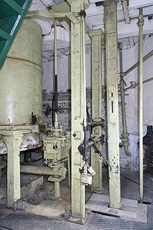 Newcomen-style engine at the Elsecar Heritage Centre, in 2006
The main problem with the Newcomen design was that it was very expensive to operate. After the cylinder was cooled to create the vacuum, the cylinder walls were cold enough to condense some of the steam as it was sprayed in. This meant that a considerable amount of fuel was being used just to heat the cylinder back to the point where the steam would start to fill it again. As the heat losses were related to the surfaces, while useful work related to the volume, increases in the size of the engine increased efficiency. Newcomen engines became larger in time. However, efficiency did not matter very much within the context of a colliery, where coal was freely available. Attempts were made to drive machinery by Newcomen engines, but these were unsuccessful, as the single power stroke produced a very jerky motion.
Newcomen's engine was only replaced when James Watt improved it in 1769 to avoid this problem (Watt had been asked to repair a model of a Newcomen engine by Glasgow University. A model exaggerated the scale problem of the Newcomen engine). In the Watt steam engine, condensation took place in a separate container, attached to the steam cylinder via a pipe. When a valve on the pipe was opened, the vacuum in the condensor would, in turn, evacuate that part of the cylinder below the piston. This eliminated the cooling of the main cylinder, and dramatically reduced fuel use. It also enabled the development of a reciprocating engine, with upwards and downwards power strokes more suited to transmitting power to a wheel.
Watt's design, introduced in 1769, did not eliminate Newcomen engines immediately. Watt's vigorous defence of his patents resulted in the desire to avoid royalty payments as far as possible.
The expiry of the patents led to a rush to install Watt engines in the 1790s, and Newcomen engines were eclipsed, even in collieries.
Surviving examples
In 1986, a full-scale working replica of the Newcomen steam engine was completed at the Black Country Living Museum in Dudley. It is the only full-size working replica of the engine in existence.[15]
The 'Newcomen Memorial Engine' can be seen operating in Newcomen's home town of Dartmouth, where it was moved in 1963 by the Newcomen Society. This is believed to date from 1725, when it was initially installed at the Griff Colliery near Coventry.
The only Newcomen-style engine still extant in its original location is at what is now the Elsecar Heritage Centre, near Barnsley in South Yorkshire. This was probably the last commercially-used Newcomen-style engine, as it ran from 1795 until 1923. Currently it is not operational.
Other examples are in the Science Museum (London) and the Ford Museum, Dearborn, USA, amongst other places.
See also
References
- ^ "Science Museum - Home - Atmospheric engine by Francis Thompson, 1791". www.sciencemuseum.org.uk. http://www.sciencemuseum.org.uk/objects/motive_power/1920-124.aspx. Retrieved 2009-07-06.
- ^ University of Rochester, NY, The growth of the steam engine online history resource, chapter one.
- ^ Century of Inventions
- ^ The Miners Friend
- ^ Figuer, Louis "Merveilles de la science" Furne Jouvet et Cie, Paris 1868. Vol 1, pp. 53,54
- ^ Earl, Bryan (1994). Cornish Mining: The Techniques of Metal Mining in the West of England, Past and Present (2nd ed.). St Austell: Cornish Hillside Publications. p. 38. ISBN 0-9519419-3-3.
- ^ J. H. Andrew and J. S. Allen, 'A confirmation of the location of the 1712 "Dudley Castle" Newcomen engine at Coneygree, Tipton' International Journal for the history of Engineering and Technology 72(2) (2009), 174-182.
- ^ Suhail Rana, 'New evidence supporting Wolverhampton as the location of the first working Newcomen engine' International Journal for the history of Engineering and Technology 72(2) (2009), 162-173.
- ^ Dionysius Lardner, The steam engine familiarly explained and illustrated
- ^ "Chapter 7: Second Patent". www.history.rochester.edu. http://www.history.rochester.edu/steam/carnegie/ch7.html. Retrieved 2009-07-06.
- ^ "Science and Society Picture Library - Search". www.scienceandsociety.co.uk. http://www.scienceandsociety.co.uk/results.asp?image=10280720&wwwflag=2&imagepos=4. Retrieved 2009-07-06.
- ^ Rolt, L. T. C. (1963). Thomas Newcomen - The Prehistory of the Steam Engine. Dawlish: David & Charles. p. 86.
- ^ P. Belford, 'Sublime cascades: Water and Power in Coalbrookdale' Industrial Archaeology Review 29(2) (2007), 136.
- ^ B. Trinder, Industrial Revolution in Shropshire (3rd edn, Phillimore, Chichester, 2000), 48.
- ^ Black Country Living Museum: Newcomen Steam Engine
Further reading
- Rolt, L. T. C.; J. S. Allen (1977). The Steam Engine of Thomas Newcomen. Hartington: Moorland. pp. 160. ISBN 0882021710.
- Reprint: Rolt, L. T. C.; J. S. Allen (1998). The Steam Engine of Thomas Newcomen. Ashbourne Derbs: Landmark Publishing. pp. 160. ISBN 190152244X.
- Kanefsky, John; John Robey (1980). "Steam Engines in 18th-Century Britain: A Quantitative Assessment". Technology and Culture 21 (2): 161–186. doi:10.2307/3103337. ISSN 0040165X. JSTOR 3103337.
- Hulse, David K. (1999). The early development of the steam engine. Leamington Spa, UK: TEE Publishing. ISBN 0857611071.
External links
 This article incorporates text from a publication now in the public domain: Chisholm, Hugh, ed (1911). Encyclopædia Britannica (11th ed.). Cambridge University Press.Categories:
- Industrial Revolution
- Beam engines
- Stationary steam engines
- Steam engines
- Piston engines
- History of the steam engine


Wikimedia Foundation. 2010.