- Dynamic logic (digital electronics)
-
For the subject in theoretical computer science, see dynamic logic (modal logic).
In integrated circuit design, dynamic logic (or sometimes clocked logic) is a design methodology in combinatorial logic circuits, particularly those implemented in MOS technology. It is distinguished from the so-called static logic by exploiting temporary storage of information in stray and gate capacitances.[1] It was popular in the 1970s and has seen a recent resurgence in the design of high speed digital electronics, particularly computer CPUs. Dynamic logic circuits are usually faster than static counterparts, and require less surface area, but are more difficult to design, and have higher power dissipation.[2][3] When referring to a particular logic family, the dynamic adjective usually suffices to distinguish the design methodology, e.g. dynamic CMOS[4] or dynamic SOI design.[2]
Dynamic logic is distinguished from so-called static logic in that dynamic logic uses a clock signal in its implementation of combinational logic circuits. The usual use of a clock signal is to synchronize transitions in sequential logic circuits. For most implementations of combinational logic, a clock signal is not even needed.
The static/dynamic terminology used to refer to combinatorial circuits should not be confused with how the same adjectives are used to distinguish memory devices, e.g. static RAM from dynamic RAM.[5]
Contents
Terminology
In the context of logic design, the term dynamic logic is more commonly used as compared to clocked logic, as it makes clear the distinction between this type of design and static logic. To additionally confuse the matter, clocked logic is sometimes used as a synonym for sequential logic. This usage is nonstandard and should be avoided.
Static versus dynamic logic
The largest difference between static and dynamic logic is that in dynamic logic, a clock signal is used to evaluate combinational logic. However, to truly comprehend the importance of this distinction, the reader will need some background on static logic.
In most types of logic design, termed static logic, there is at all times some mechanism to drive the output either high or low. In many of the popular logic styles, such as TTL and traditional CMOS, this principle can be rephrased as a statement that there is always a low-impedance path between the output and either the supply voltage or the ground. As a sidenote, there is of course an exception in this definition in the case of high impedance outputs, such as a tri-state buffer; however, even in these cases, the circuit is intended to be used within a larger system where some mechanism will drive the output, and they do not qualify as distinct from static logic.
In contrast, in dynamic logic, there is not always a mechanism driving the output high or low. In the most common version of this concept, the output is driven high or low during distinct parts of the clock cycle.
Dynamic logic requires a minimum clock rate fast enough that the output state of each dynamic gate is used before it leaks out of the capacitance holding that state, during the part of the clock cycle that the output is not being actively driven.
Static logic has no minimum clock rate—the clock can be paused indefinitely. While it may seem that doing nothing for long periods of time is not particularly useful, it leads to two advantages:
- being able to pause a system at any time makes debugging and testing much easier, enabling techniques such as single stepping.
- being able to run a system at extremely low clock rates allows low-power electronics to run longer on a given battery.
In particular, although many popular CPUs use dynamic logic [6], only static cores -- CPUs designed with fully static CMOS technology -- are usable in space satellites due to their higher radiation hardness[7]
Dynamic logic, when properly designed, can be over twice as fast as static logic. It uses only the faster N transistors, which improve transistor sizing optimizations. Static logic is slower because it has twice the capacitive loading, higher thresholds, and uses slow P transistors for logic. Dynamic logic can be harder to work with, but it may be the only choice when increased processing speed is needed. Most electronics running at over 2 GHz these days[when?] require the use of dynamic, although some manufacturers such as Intel have completely switched to static logic to save on power[8].
In general, dynamic logic greatly increases the number of transistors that are switching at any given time, which increases power consumption over static CMOS[8]. There are several powersaving techniques that can be implemented in a dynamic logic based system. In addition, each rail can convey an arbitrary number of bits, and there are no power-wasting glitches. Power-saving clock gating and asynchronous techniques are much more natural in dynamic logic.
Dynamic logic example
As an example, consider first the static logic implementation of a NAND gate (here in CMOS):
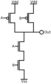
This circuit implements the logic function
If A and B are both high, the output will be pulled low, whereas if one of A and B are low, the output will be pulled high. Most importantly, though, at all times, the output is pulled either low or high.
Consider now a dynamic logic implementation:

The dynamic logic circuit requires two phases. The first phase, when Clock is low, is called the setup phase or the precharge phase and the second phase, when Clock is high, is called the evaluation phase. In the setup phase, the output is driven high unconditionally (no matter the values of the inputs A and B). The capacitor, which represents the load capacitance of this gate, becomes charged. Because the transistor at the bottom is turned off, it is impossible for the output to be driven low during this phase.
During the evaluation phase, Clock is high. If A and B are also high, the output will be pulled low. Otherwise, the output stays high (due to the load capacitance).
Dynamic logic has a few potential problems that static logic does not. For example, if the clock speed is too slow, the output will decay too quickly to be of use.
A popular implementation is domino logic.
References
- ^ Lars Wanhammar (1999). DSP integrated circuits. Academic Press. p. 37. ISBN 9780127345307. http://books.google.com/books?id=O88sXLox7tAC&pg=PA37.
- ^ a b Andrew Marshall; Sreedhar Natarajan (2002). SOI design: analog, memory and digital techniques. Springer. p. 125. ISBN 9780792376408. http://books.google.com/books?id=EgXw8sjIX0oC&pg=PA125.
- ^ A. Albert Raj, T. Latha. VLSI Design. PHI Learning Pvt. Ltd.. p. 167. ISBN 9788120334311. http://books.google.com/books?id=Fg3PBibITjAC&pg=PA167.
- ^ Bruce Jacob; Spencer Ng; David Wang (2007). Memory systems: cache, DRAM, disk. Morgan Kaufmann. p. 270. ISBN 9780123797513. http://books.google.com/books?id=G-D6KFwnVsgC&pg=PA270.
- ^ David Harris (2001). Skew-tolerant circuit design. Morgan Kaufmann. p. 38. ISBN 9781558606364. http://books.google.com/books?id=fvkIoNhAnkEC&pg=PA38.
- ^ [1]
- ^ AMSAT-DL: "No RISC, No Fun!" by Peter Gülzow
- ^ a b http://www.anandtech.com/cpuchipsets/intel/showdoc.aspx?i=3448&p=9
General references
- Sung-Mo Kang; Yusuf Leblebici (2003). CMOS digital integrated circuits: analysis and design (3rd ed.). McGraw-Hill. ISBN 9780072460537., chapter 9, "Dynamic logic circuits" (chapter 7 in the 2nd edition)
- R. Jacob Baker (2010). CMOS: Circuit Design, Layout, and Simulation (3rd ed.). Wiley-IEEE. ISBN 9780470881323., chapter 14, "Dynamic logic gates"
- Andrew Marshall; Sreedhar Natarajan (2002). SOI design: analog, memory and digital techniques. Springer. ISBN 9780792376408., chapter 7, "Dynamic SOI Design"
External links
- Introduction to CMOS VLSI Design – Lecture 9: Circuit Families – David Harris' lecture notes on the subject.
Logic families Technologies BiCMOS · CMOS · Depletion-load NMOS logic (including HMOS) · Diode logic · Diode–transistor logic (DTL) · Direct-coupled transistor logic (DCTL) · Emitter-coupled logic (ECL) · Gunning transceiver logic (GTL) · Integrated injection logic (I2L) · NMOS logic · PMOS logic · Resistor–transistor logic (RTL) · Transistor–transistor logic (TTL)
Types Static · Dynamic · Domino logic · Four-phase logic
Categories:- Logic families


Wikimedia Foundation. 2010.