- 12-inch coast defense mortar
-
The coast defense mortar was a massive weapon of 12-inch caliber emplaced during the 1890s and early 1900s to defend U.S. harbors from seaborne attack. In 1886 when the Endicott Board set forth its plan for upgrading the coast defenses of the United States, it relied primarily on mortars, not guns, to defend American harbors.[1] Over the years, provision was made for fortifications that would mount some 476 of these weapons, although not all of these tubes were installed.[2] Today, the only remaining mortars of this type in the 50 states exist at Battery Laidley, part of Fort Desoto in Florida, but the remains of coast defense mortar emplacements can be seen at many Coast Artillery forts across the United States and its former territories.
Contents
The weapons
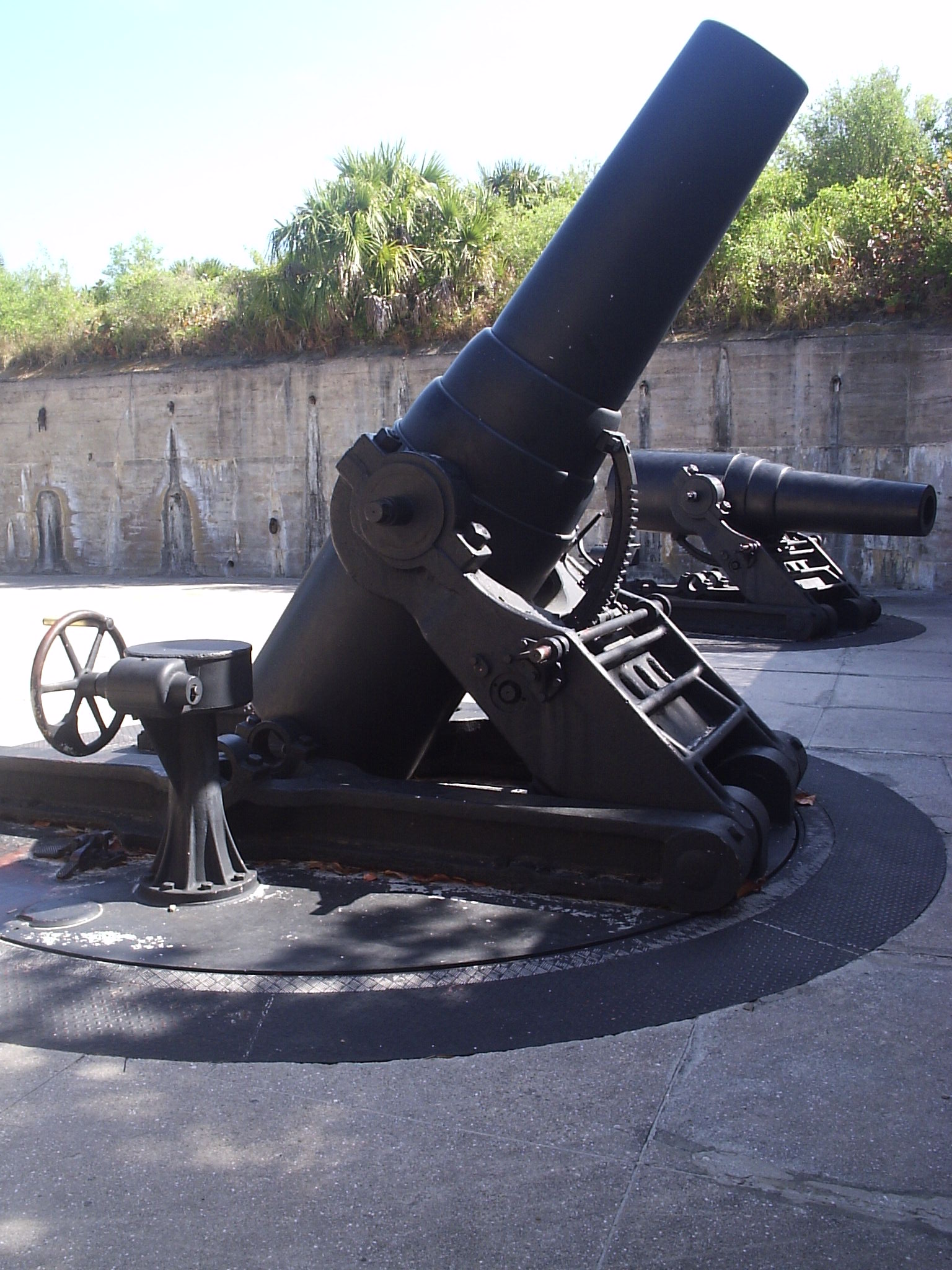
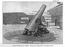 This mortar, the 1890M1, was the most common type employed.
 An 1890 M1 12-inch mortar elevated to firing position. The mortar in the background has been depressed to loading position.
]
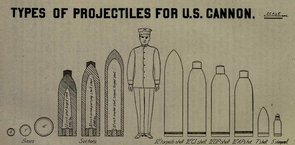
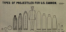 A scaled drawing of the early types of shells fired by the 12-inch mortar.
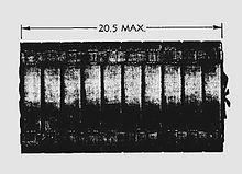 A powder load for the M1890 mortar, made of up to 10 small bags of power strapped together. A larger powder load made the shell travel further.
The 1890 M1 (Model 1) 12-inch mortar was one of the most powerful coast artillery pieces of its era, and was the most common type emplaced to guard U.S. harbors.
This mortar, and its later model, the M1908 usually fired deck-piercing (also called armor-piercing) shells. These weighed from 700 to 1,046 pounds (320 to 474 kg) and had heavy, hardened steel caps, designed to pierce a ship's deck armor before the shell exploded.[3] These mortars, firing the half-ton shells at an elevation of 45 degrees, had a range of 12,019 yards (10.990 km) (about 7 miles).[4]
The deck-piercing shells were usually the ammunition of choice, because even the heaviest battleships of the 1890-1920 period were relatively lightly armored on the tops of their main decks, so a plunging half-ton shell could inflict crippling damage on one of them.[5] Early on (from about 1890 to 1915), coast defense mortars were also supplied with so-called "torpedo shells" weighing 800 or 1,000 pounds (360 or 450 kg). (see illustration at right, below). These were thin-walled shells roughly 5 feet (1.5 m) in length that carried explosive charges of about 130 pounds (59 kg) and were meant to detonate upon contact with the deck of a ship, scattering fragments among the crew.
The M1890M1 mortar was most often installed on an M1896 carriage (as shown here in the images at top left and right).[6] The mortar and its carriage weighed a total of 78.5 tons. The carriage was geared to enable it to be turned (in azimuth) by means of a traversing crank with two handles, located on the right side of the piece. A ring marked in degrees of azimuth ran around the mortar, just outside the inner steel circle or "racer" that carried the carriage, and a soldier read a pointer on the racer to aim the mortar in direction.[7] The tube was raised or lowered (in elevation) by twin geared wheels with long spokes (resembling ship's wheels) that were located on either side of the carriage. The breech could be rapidly depressed to an almost level position for loading and then be quickly elevated for firing.[8]
In addition to the elevation of its tube, the factor that determined the mortar's range was the size of the powder charge that was loaded into its breech, following the shell. The desired range for the mortar was specified in terms of zones. The smallest zone (shortest range) was Zone 1, and the largest (longest range) was Zone 9. With the so-called "aliquot charge" (shown in the photo at right), up to 9 equal-sized, disk-shaped bags of powder (each about 2 inches (51 mm) thick and containing 6.3 pounds (2.9 kg) of powder) could be attached to a 10th (or "base") bag, by means of cloth binding straps that were sewn to the base bag. Often the base bag was painted red, indicating that the powder assembly was to be loaded into the breech "red end last," so that it bumped up against the closing breech block (or faced the gunner). The red base bag also contained a small charge of black powder as an igniter. When the breech was closed, a detonator was inserted through the breech block and contacted the igniter, ready to set off the full powder charge.
 Mortar firing circuit switches and magneto mounting shoe outside data booth, Btty Whitman Pit B, Ft. Andrews
The mortar could be fired in one of two ways: either electrically or manually (by the pull of a lanyard). And each method had its own type of detonator (electrical or friction). Electrical firing required first that the crew attach a wire to the electrical detonator, which protruded from the breech block. Second, the crew had to connect the firing cable coming out of the pit floor to the carriage of the individual mortar, out in the pit. Third, the circuit switch (usually located on the wall of the pit near the data booth) leading to the individual mortar had to be thrown into the closed (firing) position. Finally, the firing magneto, which was mounted on a special "shoe", often on the wall of the pit near the data booth, had to be cranked up and then released, sending the firing current out to the pit. Depending on the switch settings, the mortars in a given pit could be fired one at a time or all together. Lanyard firing had fewer fail-safe features, and was accomplished by a crewman who stood well behind the breech and pulled smartly on the lanyard to fire the individual mortar.
How the mortar emplacements were designed
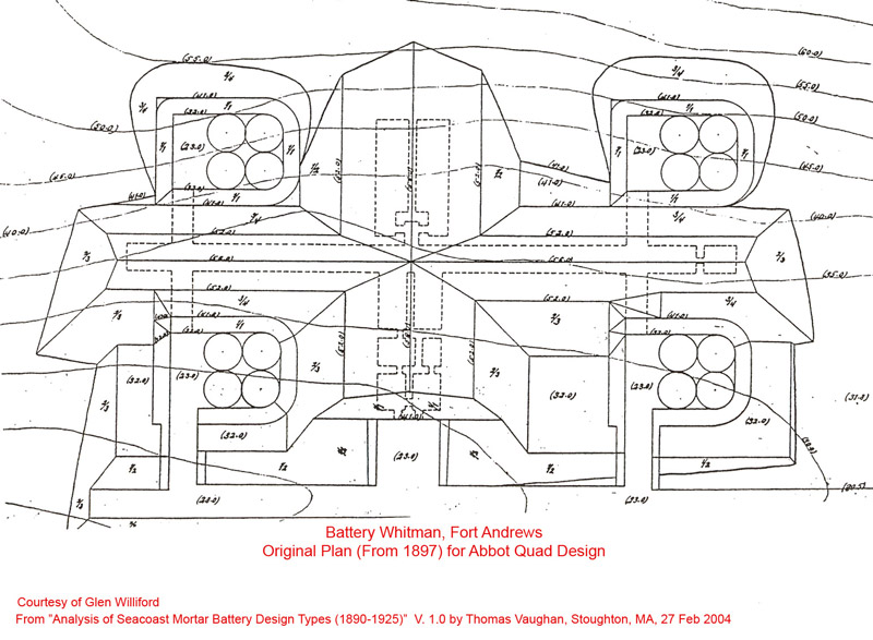
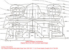 This was the original "Abbot Quad" plan for Btty Whitman, Ft. Andrews.
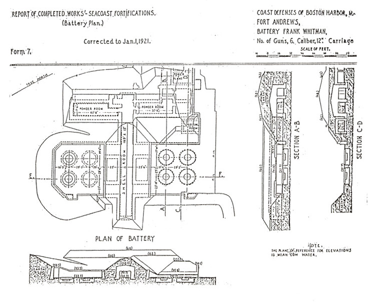
 This later plan for Btty Whitman at Ft. Andrews enlarged the pits and kept only half of the original battery.
The earliest coast defense mortar batteries of the modern era were designed (starting in about 1892) as so-called "Abbot Quads".[9] Named for Gen. Henry Larcom Abbot, the Army engineer who invented the design, Abbot Quads were rectangular configurations of four rectangular mortar pits,[10] with each pit designed to mount four of the huge mortars. A plan for an Abbot Quad mortar battery is shown at left.
The idea behind the Abbot Quad was to have all 16 mortars in the four pits fire at once, producing a shotgun-like salvo of plunging shells optimally dispersed to destroy an enemy ship.[11] It was argued that targeting each mortar individually would not produce many more hits than salvo firing, since early fire control procedures and equipment were often error-prone. Furthermore, proponents of salvo firing pointed out that it made for easier command and control (particularly under battle conditions), since all mortars in all pits of a battery could be given the same firing data. Early battery designs often contained one central "firing room" from which cables ran out to the various mortar pits, enabling electrical firing of all weapons simultaneously.[12]
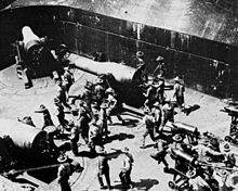 This photo shows a mortar pit of the Abbot Quad period. Three of four mortars and 30 crewmen are visible in the crowded space.
 Later designs often mounted only two mortars in a single pit, like these at Fort Wright on Long Island Sound, NY.
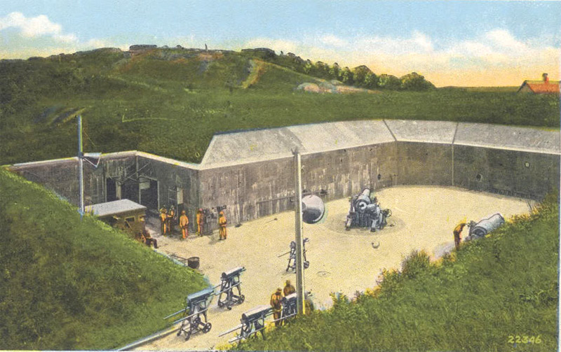
 A more panoramic postcard view of a two-mortar pit at Fort Wright.
However, the early Abbot Quad designs featured very small mortar pits. Often, four mortars were mounted in a pit that was only about 40 by 50 feet (12 by 15 m) in size.[13] Four circular areas about 18 feet (5.5 m) in diameter would fit into one of these early pits, producing a very crowded situation (given that two adjacent M1890 mortars mounted in such a pit would have their muzzles almost touching if they were traversed to face each other). A photo of such an early "crowded pit" is shown at left.
When a mortar battery was fully manned, formal guidelines called for a pit containing just two mortars (see photo at right) to be manned by a pit commander, two mortar squads of 17 enlisted men each, and an ammunition squad of 16 enlisted men.[14] One of the last versions of the manual[15] for the 12-inch mortar gives details on how it was to be crewed and fired.
After about 1905, reliance on the Abbot Quad design declined.[16] Some artillery officers[17] argued strongly that salvo firing was inherently wasteful, and that a much better hit ratio could be achieved by aiming each mortar individually against a specified target. They also argued that the smaller, cramped mortar pits of the early Abbot Quad battery designs were simply too crowded for efficient operations, with mortar crews for different tubes constantly getting in each others' way.
As fire control methods improved and the network of base end stations was extended, from about 1905 on, individual aiming of mortars could be more accurate. At the same time, designs for new pits often specified only two mortars per pit, and many forts constructed their mortar pits side-by-side. Many 4-mortar pits were "depopulated," and some of their tubes were sent away to equip newer batteries. The Abbot Quad designs passed from favor.
In 1930 the US Army tested 12 inch mortars that were train based that could be moved to different locations of the country in a time of crisis. [18]
Firing the mortars
The Coast Defense Study Group (CDSG) has found and posted this unique film clip that dates from around 1915 and shows (during its first 3 minutes or so) a firing drill on the 12-inch mortars of Battery Howe, part of the harbor defenses of San Francisco. Although the battery shown is a linear one, the firing drill is similar to what would have taken place in a square or rectangular pit.at Fort Banks. The film clip clearly illustrates how congested one of the old-style pits would have become if used to fire four mortars simultaneously (or nearly so).
The film shows the heavy shells (on shell carts) being wheeled up to the breeches of the mortars and being rammed home, the powder bags being tossed into the breeches after them, the crew clearing the immediate area while the chief of the breech raises his arm to indicate "ready to fire," and the mortars being fired electrically (from outside the area pictured). The tubes and then depressed, crewmen rush back in to swab out the tubes, the tubes are elevated, and crewmen back off ("taking cover"), firing occurs, and the process repeats itself.
The shock wave from firing just one of these huge mortars, particularly if it was fired within one of the smaller, old-style pits, was often so strong that it destroyed sensitive equipment mounted near the pit, knocked doors off of nearby magazines and barracks buildings, and broke windows in neighborhoods that were near the mortar batteries. The thundering crash of four of these mortars being fired simultaneously in a pit must have been overwhelming.
Fire control
 A data booth serving a mortar pit. The display board posted azimuth, elevation, and powder charge data for the mortars.
 A freestanding data booth at Ft. Andrews, Boston, MA.
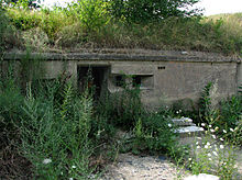 This data booth at Btty Kellogg, Ft. Banks, Winthrop, MA is built into the wall of mortar pit B.
The images here show another feature of the mortar pits—the data booth. Personnel in this small space, with its tapered viewing slits, received the coordinates (azimuth and elevation) that had been calculated via plotting board by the battery's Range Unit as the firing coordinates for the mortars in order for them to hit their targets.
These booths were either small, free-standing structures, about 10 feet (3.0 m) square and 7 feet (2.1 m) tall (as shown here in the topmost photos), or were built into one of the walls of the mortar pit itself (lower photo at right). The reconstructed data board in the photo at left hangs off the side of the data booth and is used to post the firing coordinates for mortars #3 and #4 in its pit (evidently the only two mortars there). The "Zone" number posted on the board refers to the size of the powder charge to be loaded for the coming shot (as discussed above). The top photo at right shows a decomposed set of slats (which likely used to have slates attached to them) that could have firing data chalked onto them and then be slid out of the data booth so they could be seen by the mortar crews in the pit.
Since crews of the mortars could not see their targets, they were especially dependent on the overall fire control system, with its base end stations and plotting room, to locate and pinpoint targets for them to hit.
See also
- Battery Way
- List of heavy mortars
- List of U.S. Army weapons by supply catalog designation SNL E-13
References
- ^ The Board recommended "581 high power guns of heavy calibers and 724 heavy rifled mortars. In a total of 1,305 heavy guns 55.5% [were] mortars." See "Sea-Coast Mortar Fire," Report of a Board, in Journal of the United States Artillery, Vol. 7, No. 3, 1897.
- ^ Nevertheless, a quick search of the web indicates that this weapon was the largest caliber and most widely deployed mortar in service anywhere in the world.
- ^ See Bolling W. Smith, "Coast Artillery Projectiles, 1892-1915," The Coast Defense Study Group Journal, Vol 9, No. 1, February, 1995. p.16.
- ^ See "The Service of Coast Artillery," Frank T. Hines and Franklin W. Ward, Goodenough & Woglom Co., New York, 1910, p. 119.
- ^ The half-ton deck-piercing mortar shells could penetrate between 6 and 12 inches (150 and 300 mm) of armor plate, depending upon the maximum height to which they were shot. Since shells shot at close range did not travel high enough to attain deck-piercing momentum, these mortars were generally not effective at close range. See Smith, supra, Note No. 3
- ^ The M1896 carriage had massive recoil springs that extended into a 5-foot-deep (1.5 m) circular pit below the mortar's circular base (which was 14 ft in diameter). At almost all the former mortar batteries in the U.S., however, these mounting pits have now been filled in and capped with concrete, leaving only a "new-ish" concrete circle to mark the former position of the mortar.
- ^ A crew man was tasked with using chalk to mark on the azimuth circle each new azimuth the was fired, a step that was supposed to help avoid hoped mistakes in aiming the piece.
- ^ A built-in interlock protected the mortar from being fired if its elevation was less than 42 degrees, preventing it from being fired at the wall of its emplacement.
- ^ For a description of all the types of U.S. coast defense mortar batteries, plans, and a discussion of differences, see "Analysis of Seacoast Mortar Battery Design Types (1890–1925), by Thomas Vaughan, Version 1.0. Stoughton. MA 27 February 2004.
- ^ Often these early pits had rounded corners and one open side which backed up to a magazine corridor or an open concrete pad, while the front side of the pit was protected by a high earthen bank or berm, making the pit invisible to attackers and almost impossible to hit from the sea.
- ^ See "Vertical Fire in Sea-Coast Batteries," by General Henry L. Abbot, Journal of the United States Artillery, Vol. V, No, 3, May-June, 1896, p. 313. The article reports on the probability of hits to be achieved by firing 4-pit, 16-mortar salvos of mortars aimed in parallel, and claims the hit rate is about 10% at 6,000 yards (5,500 m) Abbot reports that 13 shells from a 16-mortar salvo at 6,000 yards (5,500 m) fell within a rectangle 150 yards (140 m) by 200 yards (180 m) (A battleship of the era was about 125 yards (114 m) long by 25 yards (23 m) wide.) Abbot himself used the "shotgun" analogy to describe these 16-tube salvos.
- ^ It is not clear, however, if this method of simultaneous firing for multiple pits (or even for four mortars in one pit) was ever put into practice.
- ^ The pit-size examples given here and below are taken from Battery Kellogg at Ft. Banks, which was initially designed in 1892 and then redesigned about 1905.
- ^ "TR 435-422 Coast Artillery Corps: Service of the Piece, 12-Inch Mortar (Fixed Armament), (U.S.) War Department, Washington, D.C., December 24, 1924, p. 2.
- ^ 1942 version of the mortar manual
- ^ The evolution of coast defense mortar batteries is described in "Historic Inventory: Fort Banks Mortar Battery, Winthrop, Mass.", Prepared for the Fort Banks Preservation Association, by Thomas J. Vaughan, February, 2001. (Document submitted to the Massachusetts Historical Commission to [successfully] nominate the Fort Banks mortar batteries in Winthrop, MA for the National Register of Historic Places.
- ^ A Board of Review on which sat the noted artilleryman John W. Ruckman (after whom Fort Ruckman was later named) took issue with the logic of the Abbot Quad. See supra, Note #1.
- ^ "Mortar Railway Gun to Aid in Defending Coast" Popular Mechanics, December 1930
External links
Categories:- Mortars of the United States
- World War II artillery of the United States
- Coastal artillery
- Railway guns
- World War I weapons of the United States


Wikimedia Foundation. 2010.