- DMX512
-
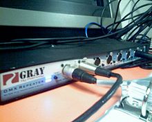 A DMX splitter/buffer. It allows many devices that are controlled by DMX to be plugged into one controller, like a lighting console
DMX512 (For "Digital Multiplex with 512 pieces of information") is a standard for digital communication networks that are commonly used to control stage lighting and effects. It was originally intended as a standardized method for controlling light dimmers, which, prior to DMX512, had employed various incompatible proprietary protocols. However, it soon became the primary method for linking not only controllers and dimmers, but also more advanced fixtures and special effects devices such as fog machines and moving lights, and has also expanded to uses in non-theatrical interior and architectural lighting; DMX512 has been used at scales ranging from strings of Christmas lights to electronic billboards.
DMX512 employs EIA-485 differential signaling at its physical layer, in conjunction with a variable-size, packet based communication protocol. It is unidirectional.
DMX512 does not include automatic error checking and correction, and so is not an appropriate control for hazardous applications,[1] such as pyrotechnics or movement of theatrical rigging. False triggering may be caused by electromagnetic interference, static electricity discharges, improper cable termination, excessively long cables, or poor quality cables.
Contents
History
DMX512
Developed by the Engineering Commission of United States Institute for Theatre Technology (USITT), the DMX512 standard (For "Digital Multiplex with 512 pieces of information"[2]) was created in 1986, with subsequent revisions in 1990 leading to USITT DMX512/1990.[citation needed]
DMX512-A
In 1998 the Entertainment Services and Technology Association (ESTA) began a revision process to develop the standard as an ANSI standard. The resulting revised standard, known officially as "Entertainment Technology—USITT DMX512-A—Asynchronous Serial Digital Data Transmission Standard for Controlling Lighting Equipment and Accessories", was approved by the American National Standards Institute (ANSI) in November 2004. It was revised again in 2008, and is the current standard known as "E1.11 - 2008, USITT DMX512-A", or just "DMX512-A", and is maintained by ESTA.
Physical layer
Network topology
A DMX512 network employs a multi-drop bus topology with nodes strung together in what is commonly called a daisy chain. A network consists of a single DMX512 controller—which is the sole master of the network—and one or more slave devices. For example, a lighting console is frequently employed as the controller for a network of slave devices such as dimmers, fog machines and intelligent moving lights.
Each slave device has a DMX512 "IN" connector and, in most cases, a DMX512 "OUT" connector (sometimes marked "THRU") as well. The controller, which has only an OUT connector, is connected via a DMX512 cable to the IN connector of the first slave. A second cable then links the OUT or THRU connector of the first slave to the IN connector of the next slave in the chain, and so on. The final, empty, OUT or THRU connector of the last slave on the daisy chain should have a terminator plugged into it.
A terminator is a stand-alone male connector with a built-in 120 Ω resistor — matching the cable characteristic impedance — connected across the primary data signal pair. If a secondary data pair is used, then another termination resistor is connected across it as well. Although simple systems, i.e., systems having few devices and short cable runs, may work without a terminator, the standard does require its use. Some DMX devices have built-in terminators that can be manually activated with a mechanical switch or by software, or by automatically sensing the absence of a connected cable.
Each DMX network is called a "DMX universe".[3] Large control desks (operator consoles) may have the capacity to control multiple universes, with an OUT connector provided for each universe.
Electrical
DMX512 data are sent using EIA-485 voltage levels. However, quoting from E1.11, "The electrical specifications of this Standard are those of EIA-485-A, except where specifically stated in this document. Where a conflict between EIA-485-A and this document exists, this document is controlling as far as this Standard is concerned."
DMX512 is a bus network no more than 1,200 metres (3,900 ft) long, with not more than 32 devices on a single bus. If more than 32 devices need to communicate, the network can be expanded across parallel buses using DMX splitters. Network wiring consists of a shielded twisted pair, with a characteristic impedance of 120 Ohms, with a termination resistor at the end of the cable furthest from the controller to absorb signal reflections. DMX-512 has two twisted pair data paths, although specification currently only defines the use of one of the twisted pairs. The second pair is undefined, but required by the electrical specification.
Some equipment manufacturers such as Chauvet and American DJ have disregarded the formal topology rules, and designed their equipment to use nonstandard 3-pin XLR connectors rather than the proper 5-pin DMX connectors, so as to eliminate the need for the unused second pair and allow for the use of regular microphone audio cables. Similarly, end users can create adapter pigtails to convert from the correct 5-pin DMX to a 3-pin XLR microphone cable. For short cable runs of less than about 45 metres (148 ft) with only a few devices, it is sometimes possible to operate without termination. At short distances, cables with higher capacitance and different characteristic impedance such as microphone cable can be used. As the cable length and/or number of devices increases however, following the specification for termination and correct cable impedance becomes of vital importance.
The E1.11 (DMX512 2004) electrical specification addresses the connection of DMX512 signal common to Earth ground. Specifically, the standard recommends that transmitter ports (DMX512 controller OUT port) have a low impedance connection between signal common and ground; such ports are referred to as grounded. It is further recommended that receivers have a high impedance connection between signal common and ground; such ports are referred to as isolated.
The standard also allows for isolated transmitter ports. Systems with the transmitter port and all receiver ports isolated are fairly common.[citation needed] The standard allows for non-isolated receivers.
Good practice dictates[citation needed] that systems ground the signal common at only one point, in order to avoid the formation of disruptive ground loops.
Grounded receivers that have a hard connection between signal common and ground are permitted but their use is strongly discouraged. Several possible grounding configurations which are commonly used with EIA485 are specifically disallowed by E1.11.[example needed]
Connectors
DMX512 1990 specifies that where connectors are used, the data link shall use five-pin XLR style electrical connectors (XLR-5), with female connectors used on transmitting (OUT) ports and male connectors on receiving ports. The use of a 3-pin XLR connector is specifically prohibited.
DMX512-A (ANSI E1.11-2008) allows the use of eight-pin modular (RJ-45) connectors for fixed installations where regular plugging and unplugging of equipment is not required.
Some DMX512 equipment manufacturers at the dawn of the DMX era employed non-compliant or proprietary connectors and pinouts; eventually, the most common of these became the already common three-pin XLR connector (also called cannon jack in some countries), since the electrical specification currently only defines a purpose for a single wire pair. There may be a risk of equipment damage if XLR 3-pin carrying DMX signal is plugged into an audio signal chain, but nevertheless some lighting fixtures and controllers are fitted with 3-pin XLR connectors exactly like the ones used in audio signal chains. These are primarily cheap or very old designs. Furthermore, some of these non-standard items have an inverse polarity for the data signal, requiring the signal wires to be swapped over.
Also, devices are sometimes fitted with four-pin connectors when both communications and power are sent through a common cable. Note also that non-theatrical uses of DMX512 such as architectural lighting often use non-standard connectors.
XLR-3 pinout
- Signal Common
- Data 1-(Primary Data Link)
- Data 1+ (Primary Data Link)
XLR-5 pinout
- Signal Common
- Data 1- (Primary Data Link)
- Data 1+ (Primary Data Link)
- Data 2- (Optional Secondary Data Link)
- Data 2+ (Optional Secondary Data Link)
RJ-45 pinout
- Data 1+
- Data 1-
- Data 2+
- Not Assigned
- Not Assigned
- Data 2-
- Signal Common (0 V) for Data 1
- Signal Common (0 V) for Data 2
The 8P8C modular connector pinout matches the conductor pairing scheme used by Category 5 (Cat5) twisted pair patch cables. The avoidance of pins 4 and 5 helps to prevent equipment damage, if the cabling is accidentally plugged into a single-line public switched telephone network phone jack.
Cabling
 Cable built to the DMX-512A specification
The cable has a male connector on one end and a female connector on the other end. The male connector plugs into the transmitting, female jack and the female connector plugs into the receiving, male jack.
Cabling for DMX512 was removed from the standard and a separate cabling standards project was started in 2003.[4] Two cabling standards have been developed, one for portable DMX512 cables (ANSI E1.27-1 - 2006) and one for permanent installations (draft standard BSR E1.27-2). This resolved issues arising from the differences in requirements for cables used in touring shows versus those used for permanent infrastructure.[5]
The electrical characteristics of DMX512 cable are specified in terms of impedance and capacitance, although there are often mechanical and other considerations that must be considered as well. Cable types that are appropriate for DMX512 usage will have a nominal characteristic impedance of 120 ohms. Cat5 cable, commonly used for networking and telecommunications, has been tested by ESTA for use with DMX512A. Also, cables designed for EIA485 typically meet the DMX512 electrical specifications. Conversely, microphone and line level audio cables lack the requisite electrical characteristics and thus are not suitable for DMX512 cabling. The significantly lower impedance and higher capacitance of these cables distort the DMX512 digital waveforms, which in turn can cause irregular operation or intermittent errors that are difficult to identify and correct.
Protocol
At the datalink layer, a DMX512 controller transmits asynchronous serial data at 250 kbaud. The data format is fixed at one start bit, eight data bits, two stop bits and no parity.
The start of a packet is signified by a break followed by a "mark" (a logical one), known as the "Mark After Break" (MAB). The break, which signals the end of one packet and the start of another, causes receivers to start reception and also serves as a frame (position reference) for data bytes within the packet. Framed data bytes are known as slots. Following the break, up to 513 slots are sent.
The first slot is reserved for a "Start Code" that specifies the type of data in the packet. A start code of 0x00 (hexadecimal zero) is the standard value used for all DMX512 compatible devices, which includes most lighting fixtures and dimmers. Other start codes are used for Text packets (0x17), System Information Packets (0xCF), for the RDM extension to DMX (0xCC), and various proprietary systems. ESTA maintains a database of alternate start codes.[6]
All slots following the start code contain control settings for slave devices. A slot's position within the packet determines the device and function to be controlled, while its data value specifies the control setpoint. Multi-byte data values are conveyed in little endian format in adjacent slots.
Timing
DMX512 timing parameters are allowed to vary over a wide range. The original authors specified the standard this way to provide the greatest design flexibility. Because of this, however, it was difficult to design receivers that operated over the entire timing range. As a result of this difficulty,[citation needed] the timing specification of the original 1986 standard was changed in 1990. Specifically, the MAB, which was originally fixed at 4 μs, was changed to 8 μs, minimum. The E1.11 (2004) standard relaxed the transmitter and receiver timing specifications. This relaxed the timing requirements for systems using controllers built to DMX512-A (E1.11); however, a significant number of legacy devices still employ transmit timing near the minimum end of the range.
-- Min Break (μs) Min MAB (μs) Transmitted 92 12 Receiver recognize 88 8 Maximum times are not specified because as long as a packet is sent at least once per second, the BREAK, MAB, inter-slot time, and the mark between the last slot of the packet and the break (MBB) can be as long as desired.
A maximum-sized packet, which has 512 channels (slots following the start code), takes approximately 23 ms to send, corresponding to a maximum refresh rate of about 44 Hz. For higher refresh rates, packets having fewer than 512 channels can be sent.
The standard does not specify the minimum number of slots that can be sent in a packet. However, it does require that packets be transmitted so that the leading edges of any two sequential BREAKs must be separated by at least 1204 μs, and receivers must be able to handle packets with break-to-break times a short as 1196 μs.[7] The minimum break-to-break transmit time can be achieved by sending packets that contain at least 24 slots (by adding extra padding bytes, if necessary) or by stretching parameters such as the BREAK, MAB, Interslot, or Interpacket times. More information on the DMX Packet is well described here [2].
Addressing and data encoding
Most data is sent with the default Null Start Code of 00h. Quoting from the standard:
8.5.1 NULL START code
A NULL START Code identifies subsequent data slots as a block of un-typed sequential 8-bit information.
Packets identified by a NULL START Code are the default packets sent on DMX512 networks. Earlier versions of this standard assumed that only dimmer class data would be sent using NULL START Code packets. In practice NULL START Code packets have been used by a wide variety of devices; this version recognizes this fact.
Each NULL START Code packet contains no formal data or addressing structure. The device using data from the packet must know the position of that data within the packet.
Dimmer packs or racks use a group of slots to determine the levels for their dimmers. Typically a dimmer has a starting address that represents the lowest numbered dimmer in that pack, and the addressing increases from there to the highest numbered dimmer. As an example, for two packs of six dimmers each, the first pack would start at address 1 and the second pack at address 7. Each slot in the DMX512 packet corresponds to one dimmer.
8-bit versus 16-bit
DMX does not mandate a method of 16-bit encoding for Null Start Code packets, however many moving lights make use of encoding larger than 8 bit numbers. To control position more accurately, some fixtures use two channels each for pan and tilt. This gives a 16-bit value range of 65536, permitting accuracies for each axis down to 0.007° (446°/65536).
DMX in practice
DMX512's popularity is partly due to its robustness. The cable can be abused without any loss of function in ways that would render Ethernet or other high speed data cables useless, although cable faults can occasionally lead to intermittent problems such as random triggering. Unexpected fixture behavior is caused by addressing errors, cable faults, or incorrect data from the controller.
Secondary data link
 The Singapore Flyer uses wireless DMX to control the lighting on the pods and rim
Although the two secondary link pins of the five-pin XLR connector were originally intended to support a second DMX512 universe, many other proprietary uses have been implemented for these pins. For example, some DMX512 equipment manufacturers used these pins to carry power (typically 24 volts DC) for their proprietary equipment, even though this violated the DMX512 specification and would potentially damage other, standard DMX512 devices on the network. Consequently the standard practice is now to send additional universes on separate connectors and leave the secondary data link pins unused.
Some manufacturers made units with three-pin connectors because of their lower cost, even though DMX512-A specifies that the connector must be a five-pin XLR connector. There is good reason for this rule: a three-pin XLR can easily be connected to a sound board. If a DMX512 controller or device were to be accidentally connected to a sound board that is generating 48 volt phantom power, the phantom power sent along the cable could potentially damage the DMX512 equipment.
Wireless operation
Recently, wireless DMX512 adapters have become popular, especially in architectural lighting installations where cable lengths can be prohibitively long. Such networks typically employ a wireless transmitter at the controller, with strategically placed receivers near the fixtures to convert the wireless signal back to conventional DMX512 wired network signals.
Although wireless DMX512 networks can function over distances exceeding 3,000 feet (910 m) under ideal conditions, most wireless DMX512 links are limited to a maximum distance of 1,000–1,500 feet (300–460 m) to ensure reliable operation. Early wireless DMX512 systems typically used WLAN technology. Later generations used frequency-hopping spread spectrum (FHSS) technology to attain more reliable data transfers, although FHSS systems tend to disturb other types of wireless communication systems such as WiFi/WLAN. This has been solved in newer wireless DMX systems by using adaptive frequency hopping and cognitive coexistence, a technique to detect and avoid surrounding wireless systems, to avoid transmitting on occupied frequencies.[8]
Development
Many alternatives to DMX512 have been proposed to address perceived limitations such as the maximum slot count of 512 per universe, the unidirectional signal, and the lack of inherent error detection. The 2004 DMX512-A revision added a System Information Packet (SIP). This packet can be interleaved with Null packets. One feature of SIPs is they allow check sums to be sent for DMX Null data. However, SIPs have rarely been implemented.
The 2004 DMX512, A revision of DMX512, also lays the foundation for the RDM (Remote Device Management) protocol through the definition of Enhanced Functionality. RDM allows for diagnostic feedback from fixtures to the controller by extending the DMX512 standard to encompass bidirectional communication between the lighting controller and lighting fixtures. RDM was approved by ANSI in 2006 and is rapidly gaining popularity.
An Ethernet based protocol can distribute multiple DMX universes through a single cable from a control location to breakout boxes closer to fixtures. These boxes then output the conventional DMX512 signal. ANSI E1.31—2009[5] Entertainment Technology—Lightweight streaming protocol for transport of DMX512 using ACN, published May 4, 2009, and Art-Net are two free-to-use protocols used to achieve this.
See also
References
- ^ United States Institute for Theatre Technology -- Resources > Standards > DMX512 > DMX512 FAQ -- http://www.usitt.org/Resources/Standards2/DMX512/DMX512FAQ#a12 -- ...DMX512 is not an appropriate control protocol for hazardous applications...
- ^ United States Institute for Theatre Technology DMX512 FAQ
- ^ Bennette, Adam (2006). Recommended Practice for DMX512. pg. 89: PLASA. ISBN 978-0-9557035-2-2.
- ^ http://tsp.plasa.org/tsp/working_groups/CP/docs/CPmin07-2003w.pdf
- ^ a b PLASA Technical Standards Program [1]
- ^ http://www.esta.org/tsp/working_groups/CP/DMXAlternateCodes.php
- ^ ESTA (2004). American National Standard E1.11 - 2004. [Entertainment Services and Technology Association ]. p. 19.
- ^ CRMX Nova - Technology. LumenRadio AB. Retrieved on 29 March 2010
External links
Categories:- Stage lighting
- Network protocols
- ANSI standards


Wikimedia Foundation. 2010.