- Dimensionless Specific Energy Diagrams for Open Channel Flow
-
Contents
Energy Equations
Energy conservation is an important concept when analyzing open channel flows. For the purposes of the following analysis, energy is conserved for a fluid in an open channel flow, and head losses due to friction will be neglected. The energy calculated at one location in the flow will be equal to the energy calculated at any other location in the same flow.
-
E1 = E2
(
The energy for the flow will have a potential energy component calculated from the depth of water in the flow, a pressure component, and a kinetic energy component calculated from the velocity of the flow moving through the channel. This is depicted through the Bernoulli equation equation:
-

(
where:
E = energy [=] Length,
v = velocity [=] Length/Time,
g = acceleration due to gravity [=] Length/Time2,
y = depth of water in the flow [=] Length,
p = pressure [=] Force/Length2, and
γ = specific gravity of the fluid [=] Force/Length3,For two locations in the system with the datum chosen as the bottom of a channel with no slope:
-

(
For an open channel flow the fluid, water, is open to the atmosphere so that the pressure throughout the system can be considered equal to atmospheric pressure. Therefore, the pressure term will be the same (hydrostatic) at all points in the system, reducing the equation to:
-

(
For a rectangular channel the flow velocity can be related to a discharge rate per unit width, q, such that:
-

(
-

(
and
-

(
For given values of unit discharge, q, a specific energy diagram depicting energy and the depth of water, y, can be developed. The specific energy is the energy above the datum, which we have chosen as the bottom of the channel.
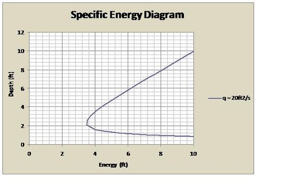 Figure1.
For each value of unit discharge, there is an associated critical depth, yc. Flow travelling at a depth greater than the critical depth is subcritical, and flow travelling at a depth less than the critical depth is supercritical. Subcritical flow has a larger potential energy component, and supercritical flow has a larger kinetic energy component. For a given energy value there will generally be two possible depths, a subcritical depth and a supercritical depth. These depths are related by the alternate depth equation:
-

(
Either alternate depth value can be found with the alternate depth equation if the unit discharge and one of the depth values is known.
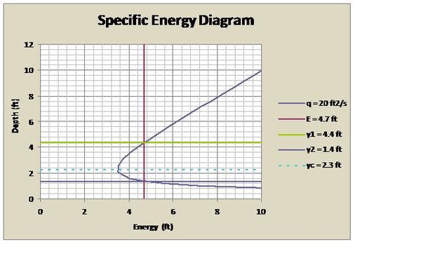 Figure2
The critical depth is the smallest energy value on the specific energy diagram. Therefore, we can take the first derivative of the energy equation with respect to depth to determine the critical depth (dE/dy) and equate it to zero to determine the minimum value.
-

(
Solving for the critical depth we obtain:
-
![y_c=\sqrt[3]{q^2 \over g}](941f87dae9265ec7a85d53ed6437c414.png)
(
and
-

(
The energy associated with the critical depth can be determined by substituting Equation 11 into Equation 7 to reveal the following:
-

(
See http://en.wikipedia.org/wiki/User:OCFGroup1 for a more detailed description of specific energy topics.
In addition the dimensionless Froude number is defined as follows:
-

(
where:
Fr =1 at critical conditions,
Fr<1 at subcritical conditions, and
Fr>1 at supercritical conditions.
Example
For a given flow in a rectangular channel with a unit discharge of 20 ft2/s and initial upstream depth of 4.4 ft (See Figure 1.) the specific energy can be calculated from Equation 7:

the critical depth can be calculated from Equation 10 as:
![y_c=\sqrt[3]{(20\frac{ft^2}{s})^2 \over 32.2\frac{ft}{s^2}}=2.3ft,](3dbc528d0d3e4207cb6ee1daadd548d3.png)
and the alternate depth downstream can be calculated from Equation 8 as:

If a sluice gate is lowered into a subcritical flow to a depth lower than the critical depth, the flow downstream of the sluice gate will become supercritical and this downstream depth will be the alternate depth as seen in the figure below where the sluice gate is lowered to a depth of 2 ft (< yc = 2.3 ft and > y2 = 1.4 ft).
 Figure3
Choke Conditions
The specific energy diagram is specific to the unit discharge for a given flow rate. For any given flow an obstruction such as a sluice gate, a step in the channel bottom, or a constriction might require more energy than the flow originally possesses, and thus a transient condition is set up where the unit discharge is temporarily reduced as the flow backs up and gains energy.
As an example of this consider a sluice gate that lowers below the alternate depth of the flow described above (1.4 ft). If the sluice gate is lowered to a depth of 1 ft, the flow described above will not be possible. The energy required to pass through the sluice gate at the flow conditions described will not be sufficient. In this case, a “choke” is encountered at the sluice gate. The energy required to pass with downstream depth of 1 ft can be calculated using Equation 7.

Since this is more energy than the initially described flow parameters (E = 4.7 ft), the flow upstream of the sluice gate will need to acquire more energy in order to pass through the opening. The only mechanism the flow has to acquire more energy is through the increase of initial upstream depth due to the choke conditions. The flow will begin to pass through the opening when it has acquired the minimum energy required to do so, the critical energy (Ec). The transient depth downstream of the sluice gate cannot be greater than the depth of the sluice gate so that y2 will now be 1 ft. The new upstream flow rate can be calculated by rearranging Equation 7 and inputting our known value of energy (4.7 ft):

The discharge under the gate will increase gradually as the flow upstream rises and the flow can pass under the gate at the depth original unit discharge rate of 20 ft2/s. The new steady state upstream depth can be calculated using Equation 8 with a downstream depth of 1 ft (max depth allowed by the gate) and the original unit discharge rate:

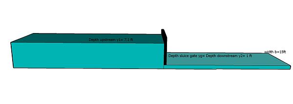 Figure4
In this example of a choke you need to evaluate depths with varying unit discharges. This can be done using the specific energy< diagram.
 Figure5
Dimensionless Diagram
Another way to evaluate a sluice gate problem is to develop the dimensionless form of this diagram dividing the energy equation by the critical depth and substituting Equation 11:
-

(
-

(


Substituting Equation 6 and Equation 11 into Equation 13 we can determine the following relationship:
-

(
-

(
With this relationship we know that values on the dimensionless E’-y’ diagram with the same value of y’ will have the same Froude number. In this way we can determine the conditions of flow.
The minimum value of E’ on the dimensionless diagram will be the first derivative of Equation 15 with respect to y’ (dE’/dy’) equated to 0 for the minimum value:
-

(
Giving y’ = 1 or yc = y at the minimum value for E’. We can determine from this that the lowest E’ value will be at the critical depth:
-


(
Considering the initial conditions with the sluice gate example above with y = 4.4 ft and yc = 2.3 ft we can calculate y’ and E’:


The dimensionless diagram representation for these conditions would be:
 Figure6
Knowing the value of y’ for the subcritical flow is 3.1, and E’ is 3.1, the alternate depth value of y’ can be determined by finding the supercritical value where the diagram crosses E’ at 2.0. From the graph, this value can be determined to be 0.60.
This can also be calculated by solving for the alternate value of y’ using Equation 15:


Solving for the alternate depth:

This is the same value we obtained above using the original specific energy diagram (with dimensions) and specific energy equation!
For the choke conditions described above with y1 = 7.1 ft and yc = 2.3 ft we can calculate y’ and E’:


The dimensionless diagram representation for these conditions would be:
 Figure7
From the graph, this value can be determined to be 0.43.
Solving for the alternate value of y’ using Equation 15:


Solving for the alternate depth:

This is the same value we assigned for y2 previously!
References
- Henderson, F.M., 1966, Open Channel Flow, Prentice-Hall.
- Chaudhry, M.H., 2008, Open Channel Flow (2nd Edition), Springer.
- Moglen, G.E., Department of Civil & Environmental Engineering, Virginia Tech, http://filebox.vt.edu/users/moglen/ocf/.
Categories: Fluid dynamics -


Wikimedia Foundation. 2010.