- Mechanical joint
-
A mechanical joint is a part of machine which are used to connect the other mechanical part or mechanism. Mechanical joints may be temporary or permanent. Most types are designed to be disassemble when required.[1]
Contents
Types Of Mechanical Joints
1.Knuckle Joints
2.Turnbuckle Joints
3.Pin Joints
4.Cotter Joints
5.Bolted joints
6.Screw Joints
7.Welded Joints[2]
Knuckle Joints
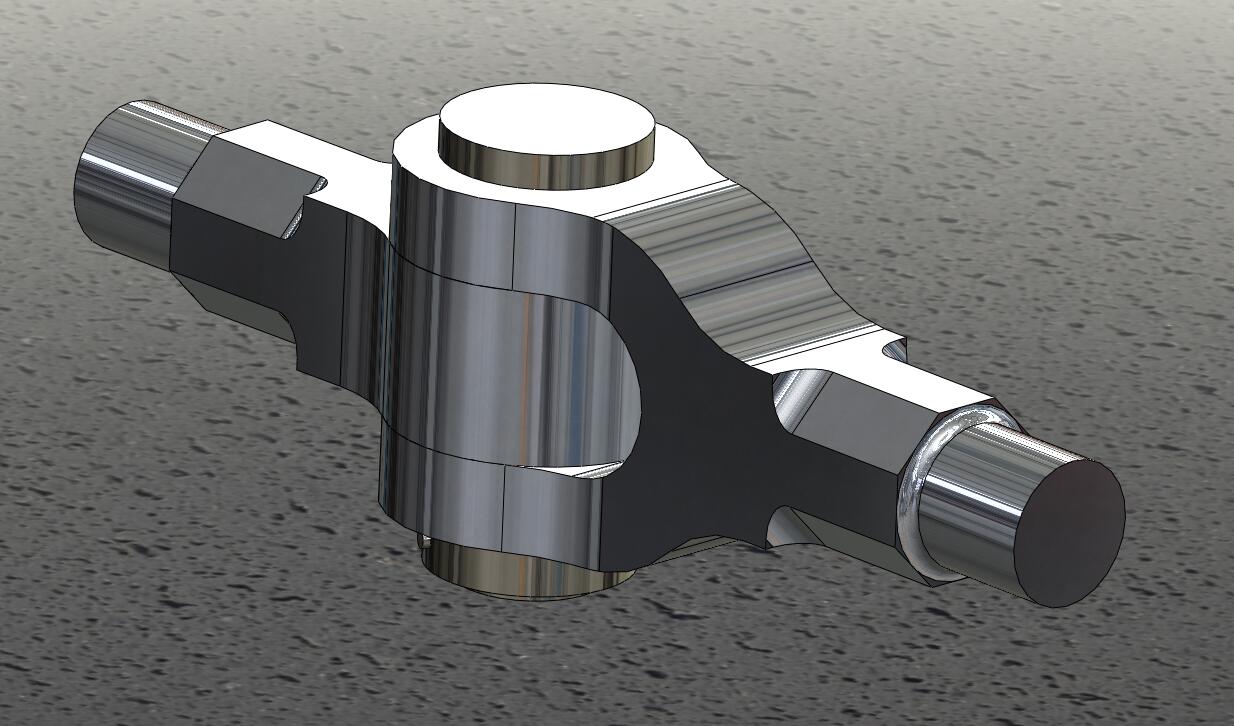
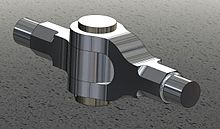 Knuckle joint
A knuckle joint is used to connect the two rods which are under the tensile load, when there is requirement of small amount of flexibility or angular moment is necessary. There is always axial or linear line of action of load.
The knuckle joint assembly consist of following major components :1.Single eye.
2.Double eye or fork.
3.Knuckle pin.
At one end of the rod the single eye is formed and double eye is formed at the other end of the rod.Both, single and double eye are connected by a pin inserted through eye.The pin has a head at one end and at other end there is a taper pin or split pin. For gripping purpose the ends of the rod are of octagonal forms.Now, when the two eyes are pulled apart, the pin holds them together .The solid rod portion of the joint in this case is much stronger than the portion through which the pin passes.[3]
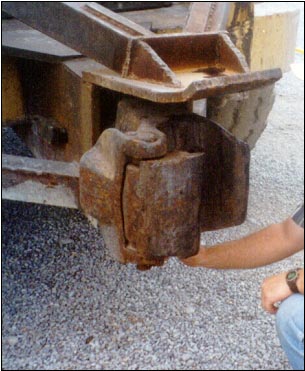
 Application of knuckle joint in tractor
The modes of failure are :1.Shear failure of pin (single shear).
2.Crushing of pin against rod.
3.Tensile failure of flat end bar.
Application :
1.Tie rod joint of roof truss.2.Tension link in bridge structure.
3.Link of roller chain.
4.Tie rod joint of jib crane.
5.The knuckle joint is also used in tractor.[4]
Design of knuckle joint
The assembly diagram of knuckle joint is as shown in fig.
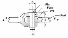 Design of knuckle joint
The dimension of knuckle joints are
Diameter of rod = d
Diameter of knuckle pin = dp
Outside diameter of single eye = doe
Outside diameter of double eye = dod
Thichness of single eye = t
Thickness of fork = t1
Axial tensile force on rod = P
(1) Diameter of rod
Consider the rod is subjected to a direct tensile stressς = P /πd2
From above equation ,diameter of rod 'd' is obtained.
(2) Design of pin (dp)
(a) Consider the failure of pin under double shear due to tensile force.
Therefore, direct shear stress induced in knuckle pin is given by Equationς= P/ 2A = (P/2) × (Π/4)dp2 = 2P/ Πdp2
(b) Failure of knuckle pin in bending
Assume there is no clearance or slack but in actual, knuckle pin is loose in forks to permit angular moment of one with respect to other, so it is subjected to bending moment in addition to shear, consider uniformly distributed load along the portion of pin.Taking moment about axis XX
M = [(-P/2) × (t/4)] + { (P/2) × [ (t2/2)+(t1/3) ] }
= P/2 [(t1/3)+(t/2)-(t1/4) ]
=P/2 [ (t1/3)+(t/4) ]
Section modulus,Z=(π/ 32)dp3
Maximum bending stress, σb
σb= M/Z = { P/2 [(t1/3)+(t/4)] } / {(π/ 32)dp3}
Here,we check the pin in bending and find the value of dp
(3) Design of single eye :
(a) To find the outside diameter diameter of single eye (doe) The single eye is subjected to a direct tensile stress, due to this single eye under tear.σt = P/A = P/ (doe-dp)× t
(b) Due to direct tensile strength, the single eye is subjected to double shear.Resisting shearing area = 2(doe-dp)×(t/2)
The direct shear stress induced is
ς=P/(doe-dp)×t
From this equation the outside diameter of single eye doe is obtained.
(C) Failure of single eye or pin due to tensile load in crushingResisting crushing area = dp × t
σc = P/(dp×t)
Form this equation crushing stress checked if fail, increase the thickness of eye (t).
(4) Design of fork (double eye):
(a) The tearing of the double eye at weakest section due to tension
Area resisting tear = (dof – dp) × 2 t1σt = p/ [(dof – dp) × 2 t1]
From this equation, find the outside diameter of fork (dof).
(b) Failure of double eye (fork) in double shear due to tensile load.
Area resisting shear = 4 × [(dof – dp) ]/2 × t1= 2 × (dof – dp) t1
The shear stress is given by,
ς = p/[(dof – dp) × 2 t1]
From this equation ,check shear stress if less than design, increase thickness of fork t1.
(c) Failure double eye in crushing (thickness of fork)
Double eye may fail in crushing due to tensile loadThe crushing stress is given by,
σc = P/( 2×dp ×t1)
Check crushing stress or find t1
TURN BUCKLE
The buckle or a coupler is a mechanical joint used to connect two members which are subjected to tensile loading which require slight adjustment of length or tension under loaded conditions. It consist of central hexagonal nut called coupler and tie rod having right hand and left hand threads. A coupler of hexagonal shape is to facilitate the turning of it with a spanner or sometime a hole is provide in the nut so that tommy bar can be inserted for rotating it. As coupler rotate, the tie rod are either pulled together or pushed apart depending upon the direction of the rotation coupler normally the tie rods are made of steel, while coupler is made of steel or C.I.
Application :1. To tighten the members of the roof truss.
2. Used to connect link in a mechanism to transfer motion
3. Used between the two railway wagon or bogies.
4. To tighten the cable or stay ropes of electric distribution poles.
Design of Turn Buckle
Consider a turnbuckle , subjected to an axial tensile force P. The various dimensions of the turnbuckle are calculated as follows:
(1) Diameter of tie rod ‘dc2 :
Due to axial tensile load p, the rod is subjected to tensile stress. Also due to twisting moment in the tie rod.The tie rod is design for direct tensile load of Pd=1.25P
The tensile stress induced in tie rod is given by
σt = 4Pd/ (π×dc×dc)
From above equation the core diameter of the tie rod is obtained. The nominal diameter can be selected from I.S.O metric screw threads table or it can be found by,
do = dc/ 0.84
(2) Length of couple nut (ln) :
Consider the direct shearing of the thread at the root of the coupler nut and the screw.(a) The direct shear stress induced in screw thread is
ςs = P/(π×dc×ln)(b) The direct shear stress induced in nut
ςn = P/ (π×do×ln)Where,
ςs and ςn = shear stress in screw and nut respectively in N/mm2
do = Nominal diameter of the screw
dc = Core diameter of the screw
ln = Length of the coupler nut
(c) Check of crushing of the thread
crushing resistance of the thread = (π/4) × [do2- dc2] ×n×ln× σcWhere,
n = number of threads per length = ln/p
σc = crushing stress induced in the coupler
p = pitch of the thread in mm
Equating the design load with crushing resistance
pd = (π/4) × [do2- dc2] ×n×ln× σc
(3) Outside diameter of the coupler nut (D) :
The coupler nut is subjected to a direct tensile load P and a torque T.Consider tearing of the coupler nut due to tensile stress induced in it. In order to account for the torque, the tensile load is taken as Pd.
The tensile stress induced in coupler nut is given by
σt = 4P/(π×(D2- do2))
By empirical relation, the outside diameter of the coupler nut D is taken as
D = 1.25 do or 1.5 do
(4) Outside diameter of coupler (D2):
Let,D1= Inside diameter of the couplerD2 = Outside diameter of the coupler
Consider a coupler is subjected to direct tensile load P and a torque T.So for design the coupler outside diameter ,the design load is consider.
By empirical relation ,
The outside diameter of the coupler D2 is taken as,
D2 = 1.5do or 1.75 do
(5) Length of the coupler nut (Ln)
Ln = 6 do
(6) Thickness of the coupler = t = 0.75 do
(7)Thickness of the coupler nut = t1 = 0.5 doCOTTER JOINT
cotter joint is used to connect the two member which are subjected to the various stress.[1] The end of the bar has a hole in it and it is called a lug. The hole carries a shaft. This shaft is locked in place by a smaller pin that passes through the side of the lug and partly or completely through the shaft itself. This locking pin is named a cotter, which sometimes is also applied to the whole joint.so this joint is called as a cotter joint.[2]. A cotter joints is a flat wedge link piece of steel of rectangular cross section which is inserted through the rods at high angle to their axes .It is uniform in thickness but tapering in width , generally on one side only. Usually the taper is 1 in 30. when a special arrangement like a set-screw is provided for keeping the cotter from slackening ,its taper may be as large as 1 in 7. the end of the cotter are made narrow to facilitate the hammering for fixing and removing.cotter joins are generally use to fasten rigidly two rod s which is subjected to tensile or compressive stress along their axes. this joint is used to connect two circular rods.This joint in not suitable where the member are subjected under rotation.Thus they differ from key joints which are used to fasten shaft and hubs subjected to tensional stress.[3]
APPLICATIONS OF COTTER :
1.Connection of the piston rod with the cross heads 2.Joining of tail rod with piston rod of a wet air pump 3.Foundation bolt 4.Connecting two halves of fly wheel (cotter and dowel arrangement) COMPARISON BETWEEN KEY AND COTTER
1.Key is usually driven parallel to the axis of the shaft which is subjected to torsional or twisting stress. Whereas cotter is normally driven at right angles to the axis of the connected part which is subjected to tensile or compressive stress along its axis. 2.A key resists shear over a longitudinal section whereas a cotter resist shear over two transverse section.
DIFFERENT TYPES OF COTTER JOINTS
1.Socket and spigot cotter joint 2.Sleeve and cotter joint 3.Gib and cotter joint
References
- ^ Blake, Alexander (1985). Design of mechanical joints. CRC Press. ISBN 978-0824773519.
- ^ Jr, [editors in chief,] Joseph E. Shigley, Charles R. Mischke, Thomas H. Brown, (2004). Standard handbook of machine design (3rd ed. ed.). New York: McGraw-Hill. ISBN 9780071441643.
- ^ Gupta, R.S. Khurmi, J.K. (2008). A textbook of machine design (S.I. units) : [a textbook for the students of B.E. / B.Tech., U.P.S.C. (Engg. Services); Section 'B' of A.M.I.E. (1)] (14th ed. ed.). Ram Nagar, New Delhi: Eurasia Publishing House. ISBN 8121925371.
- ^ Bhandari, V.B. (2001). Introduction to machine design. New Delhi: Tata McGraw-Hill. ISBN 9780070434493.
- ^ Gupta, R.S. Khurmi, J.K. (2008). A textbook of machine design (S.I. units) : [a textbook for the students of B.E. / B.Tech., U.P.S.C. (Engg. Services); Section 'B' of A.M.I.E. (1)] (14th ed. ed.). Ram Nagar, New Delhi: Eurasia Publishing House. ISBN 8121925371.
- ^ http://www.scribd.com/doc/27822626/Design-of-Turnbuckle. "Design-of-Turnbuckle".
Categories:- Engineering stubs
- Kinematics
- Rigid bodies
- Classical mechanics stubs

Wikimedia Foundation. 2010.