- Micro-Mechanics of Failure
-
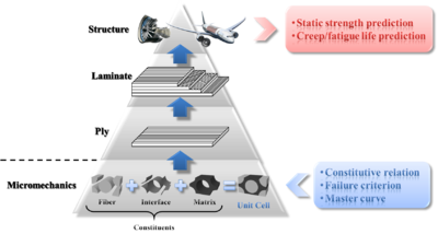 Figure 1. Hierarchy of micromechanics-based analysis procedure for composite structures.
Micro-Mechanics of Failure (MMF) is a newly proposed methodology, providing a more logical explanation of failure mechanism of continuous fiber reinforced composites than other phenomenological models such as Tsai-Wu[1] and Hashin[2][3] failure criteria. The basic concept of MMF is to perform failure analysis of fiber reinforced composites, based upon micro stresses in each constituent (fiber, matrix, and fiber-matrix interface) calculated from macro stresses at the ply level.[4] The hierarchy of micromechanics-based analysis procedure for composite structures is shown in Figure 1: starting from mechanical behavior of constituents, i.e., the fiber, the matrix, and the interface, the mechanical behavior of a ply, a laminate, and eventually a structure, can be predicted. At the constituent level, three elements are required to fully characterize each constituent:
- Constitutive relation, which describes the transient or time-independent response of the constituent to external mechanical as well as hygrothermal loadings;
- Master curve, which describes the time-dependent behavior of the constituent under creep or fatigue loadings;
- Failure criterion, which describes conditions that cause failure of the constituent.
The constituents and a unidirectional (UD) lamina are linked via a proper micromechanical model, so that ply properties can be derived from constituent properties, and on the other hand, micro stresses at the constituent level can be calculated from macro stresses at the ply level.
Contents
Unit cell model
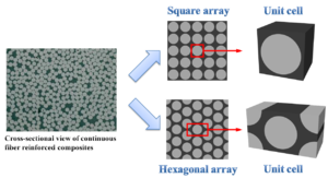 Figure 2. Schematic illustration of idealized fiber arrays and their corresponding unit cells.
Starting from the constituent level, it is necessary to devise a proper method to organize all three constituents such that the microstructure of a UD lamina is well-described. In reality, all fibers in a UD ply are aligned longitudinally; however, in the cross-sectional view, the distribution of fibers is random(Figure 2), and there is no distinguishable regular pattern in which fibers are arrayed. To avoid such a complication cause by the random arrangement of fibers, an idealization of the fiber arrangement in a UD lamina is performed, and the result is the regular fiber packing pattern. Two regular fiber packing patterns are considered: the square array and the hexagonal array (Figure 2). Either array can be viewed as a repetition of a single element, named unit cell or representative volume element (RVE), which consists of all three constituents. With periodical boundary conditions applied,[5] a unit cell is able to respond to external loadings in the same way that the whole array does. Therefore, a unit cell model is sufficient in representing the microstructure of a UD ply.
Stress amplification factor (SAF)
Stress distribution at the laminate level due to external loadings applied to the structure can be acquired using finite element analysis (FEA). Stresses at the ply level can be obtained through transformation of laminate stresses from laminate coordinate system to ply coordinate system. To further calculate micro stresses at the constituent level, the unit cell model is employed. Micro stresses
 at any point within fiber/matrix, and micro surface tractions
  at any interfacial point, are related to ply stresses
  as well as temperature increment ΔT through[6] :
-

(
, , and are columm vectors with 6, 6, and 3 components, respectively. Subscripts serve as indications of constituents, i.e. f for fiber, m for matrix, and i for interface.  and
and  are respectively called stress amplification factors (SAF) for macro stresses and for temperature increment. The SAF serves as a conversion factor between macro stresses at the ply level and micro stresses at the constituent level. For a micro point in fiber or matrix, is a 6×6 matrix while has the dimension of 6×1; for an interfacial point, respective dimensions of and are 3×6 and 3×1. The value of each single term in the SAF for a micro material point is determined through FEA of the unit cell model under given macroscopic loading conditions. The definition of SAF is valid not only for constituents having linear elastic behavior and constant coefficients of thermal expansion (CTE), but also for those possessing complex constitutive relations and variable CTEs.
Constituent failure criteria
Fiber failure criterion
Fiber is taken as transversely isotropic, and there are two alternative failure criteria for it[4]: a simple maximum stress criterion and a quadratic failure criterion extended from Tsai-Wu failure criterion:
-

(
-
Definition of coefficients in the quadratic failure criterion Coefficients involved in the quadratic failure criterion are defined as follows: 
where Xf,
 , Yf,
, Yf,  , Sf4, and Sf6 denote longitudinal tensile, longitudinal compressive, transverse tensile, transverse compressive, transverse (or through-thickness) shear, and in-plane shear strength of the fiber, respectively.
Stresses used in two preceding criteria should be micro stresses in the fiber, expressed in such a coordinate system that 1-direction signifies the longitudinal direction of fiber.
Matrix failure criterion
The polymeric matrix is assumed to be isotropic and exhibits a higher strength under uniaxial compression than under uniaxial tension. A modified version of von Mises failure criterion suggested by Christensen[7] is adopted for the matrix:
-

(
Tm and Cm represent matrix tensile and compressive strength, respectively; whereas σMises and I1 are von Mises equivalent stress and the first stress invariant of micro stresses at a point within matrix, respectively.Interface failure criterion
The fiber-matrix interface features traction-separation bahavior, and the failure criterion dedicated to it takes the following form[8] :
-

(
where tn and ts are normal (perpendicular to the interface) and shear (tangential to the interface) interfacial tractions, with Yn and Ys being their corresponding strengths. The angle brackets (Macaulay brackets) imply that a pure compressive normal traction does not contribute to interface failure.Comparison between MMF and other failure criteria
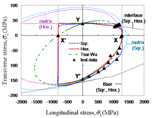 Figure 3. Comparison between theoretical failure predictions and test data.
As a completely mechanics-based failure theory, MMF outperforms other failure criteria in that it is able to distinguish the critical constituent in the critical ply in a composite laminate. The failure envelopes generated by MMF and Tsai-Wu failure criterion for a carbon/epoxy UD ply are plotted in Figure 3, with test data superimposed. Failed constituent can be directly observed from the failure envelope predicted by MMF, while the failure envelope predicted by Tsai-Wu is unable to yield such information.
Further extension of MMF
Endeavors have been made to incorporate MMF with multiple progressive damage models and fatigue models for strength and life prediction of composite structures subjected to static or dynamic loadings.
See also
- Composite material
- Strength of materials
- Failure theory (material)
- Tsai-Wu failure criterion
- Christensen Failure Criterion
References
- ^ Tsai, S.W. and Wu, E.M. (1971). A General Theory of Strength for Anisotropic Materials, Journal of Composite Materials, 5(1): 58-80.
- ^ Hashin, Z. and Rotem, A. (1973). A Fatigue Failure Criterion for Fiber Reinforced Materials, Journal of Composite Materials, 7(4): 448-464.
- ^ Hashin, Z. (1980). Failure Criteria for Unidirectional Fiber Composites, Journal of Applied Mechanics, 47(2): 329-334.
- ^ a b Ha, S.K., Jin, K.K. and Huang, Y. (2008). Micro-Mechanics of Failure (MMF) for Continuous Fiber Reinforced Composites, Journal of Composite Materials, 42(18): 1873-1895.
- ^ Xia, Z., Zhang, Y. and Ellyin, F. (2003). A Unified Periodical Boundary Conditions for Representative Volume Elements of Composites and Applications, International Journal of Solids and Structures, 40(8): 1907-1921.
- ^ Jin, K.K., Huang, Y., Lee, Y.H. and Ha, S.K. (2008). Distribution of Micro Stresses and Interfacial Tractions in Unidirectional Composites, Journal of Composite Materials, 42(18): 1825-1849.
- ^ Christensen, R.M. (2007). A Comprehensive Theory of Yielding and Failure for Isotropic Materials, Journal of Engineering Materials and Technology, 129(2): 173-181.
- ^ Camanho, P.P. and Dávila, C.G. (2002). Mixed-Mode Decohesion Finite Elements for the Simulation of Delamination in Composite Materials, NASA/TM-2002-211737: 1-37.
Categories:- Mechanics
- Solid mechanics
- Mechanical failure


Wikimedia Foundation. 2010.