- Molecular orbital diagram
-
A molecular orbital diagram, or MO diagram for short, is a qualitative descriptive tool explaining chemical bonding in molecules in terms of molecular orbital theory in general and the Linear combination of atomic orbitals molecular orbital method (LCAO method) in particular.[1][2][3] A fundamental principle of these theories is that as atoms bond to form molecules, a certain number of atomic orbitals combine to form the same number of molecular orbitals, although involved electrons may be redistributed among the orbitals. This tool is very well suited for simple diatomic molecules such as dihydrogen, dioxygen, and carbon monoxide but becomes more complex when discussing polyatomic molecules such as methane. It explains why some molecules exist and not others, how strong bonds are, and what electronic transitions can take place. In this article, MO stands for Molecular Orbital, and AO stands for Atomic Orbital.
History
Qualitative MO theory was introduced in 1928 by Robert S. Mulliken [4][5] and Friedrich Hund.[6] A mathematical description was provided by contributions from Douglas Hartree in 1928 [7] and Vladimir Fock in 1930.[8]
Basics
Molecular orbital diagrams are diagrams of MO energy levels, shown as short horizontal lines in the center, flanked on the sides by constituent AO energy levels for comparison, with the energy levels ranging from low energy at the bottom to high energy at the top. Lines, often dashed diagonal lines, connect MO levels with their constituent AO levels. Degenerate energy levels are commonly shown side by side. Appropriate AO and MO levels are filled with electrons symbolized by small vertical arrows showing the electron spin. Pictures of the AO or MO shapes themselves are often not shown on these diagrams. For a diatomic molecule, an MO diagram effectively shows the energetics of the bond between the two atoms, whose AO energies are shown on the sides as if the two atoms were free and unbonded. For simple polyatomic molecules with a "central atom" such as methane (CH4) or carbon dioxide (CO2), AO levels of the central atom may be shown on one side, and AO levels of the other atoms bonded to it shown on the other side, with the MO levels representing the bonds shown in the middle of the diagram. For other polyatomic molecules, an MO diagram may show merely a bond or some bonds of interest in the molecules, leaving others out for simplicity. Often even for simple molecules, AO and MO levels of inner orbitals and their electrons may be omitted from a diagram for simplicity.
In MO theory molecular orbitals form by overlap of atomic orbitals. The atomic orbital energy correlates with electronegativity as a more electronegative atom holds an electron more tightly thus lowering its energy. MO treatment is only valid when the atomic orbitals have comparable energy; when they differ greatly the mode of bonding becomes ionic. A second condition for mixing is that the atomic orbitals have the same symmetry.
MO diagram for dihydrogen. Here electrons are shown by dots. The two atomic orbitals can overlap in two ways depending on their phase relationship. The phase of an orbital is a direct consequence of the wave-like properties of electrons. In graphical representations of orbitals, orbital phase is depicted either by a plus or minus sign (confusing because there is no relationship to electrical charge) or simply by shading one lobe. The sign of the phase itself does not have physical meaning except when mixing orbitals to form molecular orbitals.
Then two same-sign orbitals have a constructive overlap forming a molecular orbital with the bulk of electron density located between the two nuclei. This MO is called the bonding orbital and its energy is lower than that of the original atomic orbitals. A bond involving molecular orbitals which are symmetrical with respect to rotation around the bond axis (no change) and is called a sigma bond (σ-bond). In the event of a phase change, the bond becomes a pi bond (π-bond). Symmetry labels are further defined by whether the orbital maintains its original character after an inversion about its center; if the orbital does retain its original character it is defined gerade, g, or if the orbital does not maintain its original character, ungerade, u.
Atomic orbitals can also interact with each other out-of-phase which leads to destructive cancellation and no electron density between the two nuclei at the so-called nodal plane depicted as a perpendicular dashed line. In this anti-bonding MO with energy much higher than the original AO's, any electrons present are located in lobes pointing away from the central internuclear axis. For a corresponding σ-bonding orbital, such an orbital would be symmetrical but differentiated from it by an asterisk as in σ*. For a π-bond, corresponding bonding and antibonding orbitals would not have such symmetry around the bond axis and be designated π and π*, respectively.
The next step in constructing an MO diagram is filling the newly formed molecular orbitals with electrons. Three general rules apply:
- The Aufbau principle states that orbitals are filled starting with the lowest energy
- The Pauli exclusion principle states that the maximum number of electrons occupying an orbital is two having opposite spins
- Hund's rule states that when there are several MO's with equal energy, the electrons fill into the MO's one at a time before filling two electrons into any.
The filled MO highest in energy is called the Highest Occupied Molecular Orbital or HOMO and the empty MO just above it is then the Lowest Unoccupied Molecular Orbital or LUMO. The electrons in the bonding MO's are called bonding electrons and any electrons in the antibonding orbital would be called antibonding electrons. The reduction in energy of these electrons is the driving force for chemical bond formation. Whenever mixing for an atomic orbital is not possible for reasons of symmetry or energy, a so-called non-bonding MO is created, which is often quite similar to and has energy level equal or close to its constituent AO, thus not contributing to bonding energetics. The resulting electron configuration can be described in terms of bond type, parity and occupancy for example dihydrogen 1σg2. Alternatively it can be written as a molecular term symbol e.g. 1Σg+ for dihydrogen. Sometimes, the letter n is used to designate a non-bonding orbital.
For a stable bond, the bond order defined as:

must be positive.
The relative order in MO energies and occupancy correspond with electronic transitions found in photoelectron spectroscopy (PES). In this way it is possible to experimentally verify MO theory. In general sharp PES transitions indicate nonbonding electrons and broad bands are indicative of bonding and antibonding delocalized electrons. Bands can resolve into fine structure with spacings corresponding to vibrational modes of the molecular cation (see Franck–Condon principle). PES energies are different from ionisation energies which relates to the energy required to strip off the nth electron after the first n − 1 electrons have been removed. MO diagrams with energy values can be obtained mathematically using the Hartree–Fock method. The starting point for any MO diagram is a predefined molecular geometry for the molecule in question. An exact relationship between geometry and orbital energies is given in Walsh diagrams.
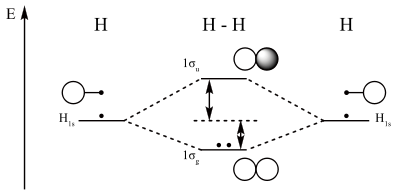
Dihydrogen MO diagram
The smallest molecule, hydrogen gas exists as dihydrogen (H-H) with a single covalent bond between two hydrogen atoms. As each hydrogen atom has a single 1s atomic orbital for its electron, the bond forms by overlap of these two atomic orbitals. In figure 1 the two atomic orbitals are depicted on the left and on the right. The vertical axis always represents the orbital energies. Each atomic orbital is singly occupied with an up or down arrow representing an electron.
Application of MO theory for dihydrogen results in having both electrons in the bonding MO with electron configuration 1σg2. The bond order for dihydrogen is (2-0)/2 = 1. The photoelectron spectrum of dihydrogen shows a single set of multiplets between 16 and 18 eV (electron volts).[9]
The dihydrogen MO diagram helps explain how a bond breaks. When applying energy to dihydrogen, a molecular electronic transition takes place when one electron in the bonding MO is promoted to the antibonding MO. The result is that there is no longer a net gain in energy.

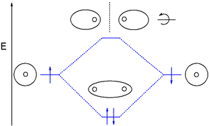
Dihelium MO diagram
Dihelium (He-He) is a hypothetical molecule and MO theory helps to explain why. The MO diagram for dihelium (2 electrons in each 1s AO) looks very similar to that of dihydrogen but instead of 2 electrons it is now required to place 4 electrons in the newly formed molecular orbitals.

The only way to accomplish this is by occupying the antibonding orbital with two electrons as well which reduces the bond order ((2-2)/2) to zero and cancels the net energy stabilization.
Another molecule that is precluded based on this principle is diberyllium (beryllium with electron configuration 1s22s2). On the other hand by removing one electron from dihelium, the stable gas-phase species He2+ ion is formed with bond order 1/2.
Dilithium MO diagram
Next up in the periodic table is lithium and MO theory correctly predicts that dilithium is a stable molecule with bond order 1 (configuration 1σg21σu22σg2). The 1s MOs are completely filled and do not participate in bonding.
Dilithium is a gas-phase molecule with a much lower bond strength than dihydrogen because the 2s electrons are further removed from the nucleus. In a more detailed analysis both the 1σ orbitals have higher energies than the 1s AO and the occupied 2σ is also higher in energy than the 2s AO (see table 1).
Diboron MO diagram
The MO diagram for diboron (B-B electron configuration boron: 1s22s22p1) requires the introduction of an atomic orbital overlap model for p orbitals. The three dumbbell-shaped p-orbitals have equal energy and are oriented mutually perpendicular (or orthogonal). The p-orbitals oriented in the x-direction (px) can overlap end-on forming a bonding (symmetrical) sigma orbital and an antibonding sigma* molecular orbital. In contrast to the sigma 1s MO's, the sigma 2p has some non-bonding electron density at either side of the nuclei and the sigma* 2p has some electron density between the nuclei.

The other two p-orbitals py and pz can overlap side-on. The resulting bonding orbital has its electron density in the shape of two sausages above and below the plane of the molecule. The orbital is not symmetrical around the molecular axis and is therefore a pi orbital. The antibonding pi orbital (also asymmetrical) has four lobes pointing away from the nuclei. Both py and pz orbitals form a pair of pi orbitals equal in energy (degenerate) and can be higher or lower than that of the sigma orbital.
In diboron the 1s and 2s electrons do not participate in bonding but the single electrons in the 2p orbitals occupy the 2πpy and the 2πpz MO's resulting in bond order 1. Because the electrons have equal energy (they are degenerate) diboron is a diradical and since the spins are parallel the compound is paramagnetic.

Dicarbon MO diagram
Like diboron, dicarbon (C-C electron configuration:1s22s22p2 MO's 2σg22σu21πu4) is a reactive gas-phase molecule. Two additional electrons are placed in the 2πp MO's increasing the bond order to 2.
Dinitrogen MO diagram
The bond order for dinitrogen (2σg22σu21πu43σg2) is three because now two electrons are added in the 3σ MO as well. The MO diagram correlates with the experimental photoelectron spectrum for nitrogen.[10] The 1σ electrons can be matched to a peak at 410 eV (broad), the 2σg electrons at 37 eV (broad), the 2σu electrons at 19 eV (doublet), the 1πu4 electrons at 17 eV (multiplets), and finally the 3σg2 at 15.5 eV (sharp).
Dioxygen MO diagram
MO treatment of dioxygen is different from that of the previous diatomic molecules because the pσ MO is now lower in energy than the 2π orbitals. This is attributed to interaction between the 2s MO and the 2pz MO.[11] Distributing 8 electrons over 6 molecular orbitals leaves the final two electrons as a degenerate pair in the 2pπ* antibonding orbitals resulting in a bond order of 2. Just as diboron, when these unpaired electrons have the same spin, this type of dioxygen called triplet oxygen is a paramagnetic diradical. When both HOMO electrons pair up with opposite spins in one orbital, the other oxygen type is called singlet oxygen.

The bond order decreases and the bond length increases in the order O2+ (112.2 pm), O2 (121 pm), O2- (128 pm) and O22- (149 pm).[11]
In difluorine two additional electrons occupy the 2pπ* with a bond order of 1. In dineon Ne2 (as with dihelium) the number of bonding electrons equals the number of antibonding electrons and this compound does not exist.
MO energies overview
Table 1 gives an overview of MO energies for first row diatomic molecules together with atomic orbital energies.
Table 1. Calculated MO energies for diatomic molecules in Hartrees [12] H2 Li2 B2 C2 N2 O2 F2 1σg -0.5969 -2.4523 -7.7040 - 11.3598 - 15.6820 - 20.7296 -26.4289 1σu -2.4520 -7.7032 -11.3575 -15.6783 -20.7286 -26.4286 2σg -0.1816 -0.7057 -1.0613 -1.4736 -1.6488 -1.7620 2σu -0.3637 -0.5172 -0.7780 -1.0987 -1.4997 3σg -0.6350 -0.7358 -0.7504 1πu -0.3594 -0.4579 -0.6154 -0.7052 -0.8097 1πg -0.5319 -0.6682 1s (AO) -0.5 -2.4778 -7.6953 -11.3255 -15.6289 -20.6686 -26.3829 2s (AO) -0.1963 -0.4947 -0.7056 -0.9452 -1.2443 -1.5726 2p (AO) -0.3099 -0.4333 -0.5677 -0.6319 -0.7300 Heteronuclear diatomics
In heteronuclear diatomic molecules, mixing of atomic orbitals only occurs when the electronegativity values are similar. In carbon monoxide (CO, isoelectronic with dinitrogen) the oxygen 2s orbital is much lower in energy than the carbon 2s orbital and therefore the degree of mixing is low. The electron configuration 1σ21σ*22σ22σ*21π43σ2 is identical to that of nitrogen. The g and u subscripts no longer apply because the molecule lacks a center of symmetry.
In hydrogen fluoride (HF), the hydrogen 1s orbital can mix with fluorine 2pz orbital to form a sigma bond because experimentally the energy of 1s of hydrogen is comparable with 2p of fluorine. The HF electron configuration 1σ22σ23σ21π4 reflects that the other electrons remain in three lone pairs and that the bond order is 1.
Carbon Dioxide MO Diagram
Carbon dioxide, CO2, is a linear molecule with a total of sixteen bonding electrons in its valence shell. Carbon is the central atom of the molecule and a principal axis, the z-axis, is visualized as a single axis that goes through the center of carbon and the two oxygens atoms. For convention, blue atomic orbital lobes are positive phases, red atomic orbitals are negative phases, with respect to the wave function from the solution of the Schrödinger equation.[13] In carbon dioxide the carbon 2s (−19.4 eV), carbon 2p (−10.7 eV), and oxygen 2p (−15.9 eV)) energies associated with the atomic orbitals are in proximity whereas the oxygen 2s energy (−32.4 eV) is different.[14]
Carbon and each oxygen atom will have a 2s atomic orbital and a 2p atomic orbital, where the p orbital is divided into px, py, and pz. With these derived atomic orbitals, symmetry labels are deduced with respect to rotation about the principal axis which generates a phase change, pi bond (π)[15] or generates no phase change, known as a sigma bond (σ).[16] Symmetry labels are further defined by whether the atomic orbital maintains its original character after an inversion about its center atom; if the atomic orbital does retain its original character it is defined gerade,g, or if the atomic orbital does not maintain its original character, ungerade, u. The final symmetry-labeled atomic orbital is now known as an irreducible representation.
Carbon dioxide’s molecular orbitals are made by the linear combination of atomic orbitals of the same irreducible representation that are also similar in atomic orbital energy. Significant atomic orbital overlap is why sp bonding may occur.[17] Strong mixing of the oxygen 2s atomic orbital is not to be expected and are non-bonding degenerate molecular orbitals. The combination of similar atomic orbital/wave functions and the combinations of atomic orbital/wave function inverses create particular energies associated with the nonbonding (no change), bonding (lower than either parent orbital energy) and antibonding (higher energy than either parent atomic orbital energy) molecular orbitals.
- MO model carbon dioxide
-

Atomic orbitals carbon dioxide
-

Molecular orbitals carbon dioxide
-

MO Diagram carbon dioxide
Water MO diagram
Water (H2O) is a bent molecule (105°) with C2v molecular symmetry. The oxygen atomic orbitals are labeled according to their symmetry as a1 for the 2s2 orbital and b2, a1 and b2 for 4 electrons in the 2p orbital. The two hydrogen 1s orbitals are premixed to form a A1 (bonding) and B2 (antibonding) MO.
C2v E C2 σv(xz) σv'(yz) A1 1 1 1 1 z x2, y2, z2 A2 1 1 −1 −1 Rz xy B1 1 −1 1 −1 x, Ry xz B2 1 −1 −1 1 y, Rx yz Mixing takes place between same-symmetry orbitals of comparable energy resulting a new set of MO's for water. The lowest-energy MO, 1a1 resembles the oxygen 2s AO with some mixing with the hydrogen A1 AO. Next is the 1b1 MO resulting from mixing of the oxygen b1 AO and the hydrogen B1 AO followed by the 2a1 MO created by mixing the a1 orbitals. Both MO's form the oxygen to hydrogen sigma bonds. The oxygen b2 AO (the p-orbital perpendicular to the molecular plane) alone forms the 1b2 MO is it is unable to mix. This MO is nonbonding. In agreement with this description the photoelectron spectrum for water shows two broad peaks for the 1b2 MO (18.5 eV) and the 2a1 MO (14.5 eV) and a sharp peak for the nonbonding 1b1 MO at 12.5 eV. This MO treatment of water differs from the orbital hybridisation picture because now the oxygen atom has just one lone pair instead of two. In this sense, water does not have two equivalent lone electron pairs resembling rabbit ears.[18]
Hydrogen sulfide (H2S) too has a C2v symmetry with 8 valence electrons but the bending angle is only 92°. As reflected in its PE spectrum as compared to water the 2a1 MO is stabilised (improved overlap) and the 1b2 MO is destabilized (poorer overlap).
External links
- MO diagrams at meta-synthesis.com Link
- MO diagrams at usm. Maine.edu Link
- MO diagrams at chem1.com Link
- Molecular orbitals at winter.group.shef.ac.uk Link
See also
- Dimolybdenum MO diagram: sextuple bond
References
- ^ Clayden, Jonathan; Greeves, Nick; Warren, Stuart; Wothers, Peter (2001). Organic Chemistry (1st ed.). Oxford University Press. pp. 96–103. ISBN 978-0-19-850346-0.
- ^ Organic Chemistry, Third Edition, Marye Anne Fox, James K. Whitesell, 2003, ISBN 978-0-7637-3586-9
- ^ Organic Chemistry 3rd Ed. 2001, Paula Yurkanis Bruice, ISBN 0-13-017858-6
- ^ Mulliken, R. (1928). "The Assignment of Quantum Numbers for Electrons in Molecules. I". Physical Review 32 (2): 186. Bibcode 1928PhRv...32..186M. doi:10.1103/PhysRev.32.186.
- ^ Mulliken, R. (1928). "Electronic States and Band Spectrum Structure in Diatomic Molecules. VII. P2→S2 and S2→P2 Transitions". Physical Review 32 (3): 388. Bibcode 1928PhRv...32..388M. doi:10.1103/PhysRev.32.388.
- ^ Hund, F. Z. Physik 1928, 51, 759.
- ^ Hartree, D. R. Proc. Cambridge. Phil. Soc. 1928, 24, 89
- ^ Fock, V. Z. Physik 1930, 61, 126
- ^ .hydrogen @ PES database arizona.edu
- ^ Bock, H.; Mollere, P. D. (1974). "Photoelectron spectra. An experimental approach to teaching molecular orbital models". Journal of Chemical Education 51 (8): 506. Bibcode 1974JChEd..51..506B. doi:10.1021/ed051p506.
- ^ a b Modern Inorganic Chemistry William L. Jolly 1985 ISBN 0-07-032760-2
- ^ Lawson, D. B.; Harrison, J. F. (2005). "Some Observations on Molecular Orbital Theory". Journal of Chemical Education 82 (8): 1205. doi:10.1021/ed082p1205.
- ^ Housecroft, C. E.; Sharpe, A. G. (2008). Inorganic Chemistry (3rd ed.). Prentice Hall. p. 9. ISBN 978-0131755536.
- ^ "An Introduction to Molecular Orbitals". Jean & volatron. ""1993"" ISBN 0-19-506918-8. p.192
- ^ Housecroft, C. E.; Sharpe, A. G. (2008). Inorganic Chemistry (3rd ed.). Prentice Hall. p. 38. ISBN 978-0131755536.
- ^ Housecroft, C. E.; Sharpe, A. G. (2008). Inorganic Chemistry (3rd ed.). Prentice Hall. p. 34. ISBN 978-0131755536.
- ^ Housecroft, C. E.; Sharpe, A. G. (2008). Inorganic Chemistry (3rd ed.). Prentice Hall. p. 33. ISBN 978-0131755536.
- ^ Laing, Michael (1987). "No rabbit ears on water. The structure of the water molecule: What should we tell the students?". Journal of Chemical Education 64: 124. doi:10.1021/ed064p124.
Categories:- Chemical bonding


Wikimedia Foundation. 2010.