- Nanogenerator
-
Nanogenerator is an energy harvesting device converting the external kinetic energy into an electrical energy based on the energy conversion by nano-structured piezoelectric material. Although its definition may include any types of energy harvesting devices with nano-structure converting the various types of the ambient energy (e.g. solar power and thermal energy), it is used in most of times to specifically indicate the kinetic energy harvesting devices utilizing nano-scaled piezoelectric material after its first introduction in 2006.[1]
Although still in the early stage of the development, it has been regarded as a potential breakthrough toward the further miniaturization of the conventional energy harvester, possibly leading the facile integration with the other types of energy harvester converting the different types of energy and the independent operation of mobile electronic devices with the reduced concerns for the energy source, consequently.
Contents
Mechanism
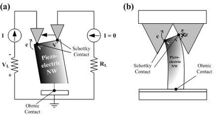 Working principle of nanogenerator where an individual nanowire is subjected to the force exerted perpendicular to the growing direction of nanowire. (a) An AFT tip is swept through the tip of the nanowire. Only negatively charged portion will allow the current to flow through the interface. (b) The nanowire is integrated with the counter electrode with AFT tip-like grating. As of (a), the electrons are transported from the compressed portion of nanowire to the counter electrode because of Schottky contact.
 Working principle of nanogenerator where an individual nanowire is subjected to the force exerted parallel to the growing direction of nanowire
The working principle of nanogenerator will be explained for 2 different cases: the force exerted perpendicular and parallel to the axis of the nanowire.
The working principle for the first case is explained by a vertically grown nanowire subjected to the laterally moving tip. When a piezoelectric structure is subjected to the external force by the moving tip, the deformation occurs throughout the structure. The piezoelectric effect will create the electrical field inside the nanostructure; the stretched part with the positive strain will exhibit the positive electrical potential, whereas the compressed part with the negative strain will show the negative electrical potential. This is due to the relative displacement of cations with respect to anions in its crystalline structure. As a result, the tip of the nanowire will have an electrical potential distribution on its surface, while the bottom of the nanowire is neutralized since it is grounded. The maximum voltage generated in the nanowire can be calculated by the following equation[2]:
![V_{\text{max}} = \pm \frac{3}{4(\kappa_0+\kappa)}[e_{\text{33}} - 2(1 + \nu) e_{\text{15}} - 2\nu e_{\text{31}}] \frac{a^3}{l^3} \nu_{\text{max}}](9/5a945f06891de20911dd21f8f5f89cde.png)
, where κ0 is the permittivity in vacuum, κ is the dielectric constant, e33, e15 and e31 are the piezoelectric coefficients, ν is the Poisson ratio, a is the radius of the nanowire, l is the length of the nanowire and νmax is the maximum deflection of the nanowire's tip.
The electrical contact plays an important role to pump out charges in the surface of the tip. The schottky contact must be formed between the counter electrode and the tip of the nanowire since the ohmic contact will neutralize the electrical field generated at the tip. In order to form an effective schottky contact, the electron affinity(Ea) must be smaller than the work function(φ) of the metal composing the counter electrode. For the case of ZnO nanowire with the electron affinity of 4.5 eV, Pt (φ=6.1eV) is a suitable metal to construct the schottky contact. By constructing the schottky contact, the electrons will pass to the counter electrode from the surface of the tip when the counter electrode is in contact with the regions of the negative potential, whereas no current will be generated when it is in contact with the regions of the positive potential, in the case of n-type semiconductive nanostructure (p-type semiconductive structure will exhibit the reversed phenomenon since the hole is mobile in this case). The formation of the schottky contact also contributes to the generation of direct current output signal consequently.
For the second case, a model with a vertically grown nanowire stacked between the ohmic contact at its bottom and the schottky contact at its top is considered. When the force is applied toward the tip of the nanowire, the uniaxial compressive is generated in the nanowire. Due to the piezoelectric effect, the tip of the nanowire will have a negative piezoelectric potential, increasing the Fermi level at the tip. Since the electrons will then flow from the tip to the bottom through the external circuit as a result, the positive electrical potential will be generated at the tip. The schottky contact will barricade the electrons being transported through the interface, therefore maintaining the potential at the tip. As the force is removed, the piezoelectric effect diminishes, and the electrons will be flowing back to the top in order to neutralize the positive potential at the tip. The second case will generate alternating current output signal.
Geometrical Configuration
Depending on the configuration of piezoelectric nanostructure, the most of the nanogenerator can be categorized into 3 types: VING, LING and "NEG". Still, there is a configuration that do not fall into the aforementioned categories, as stated in other type.
Vertical nanowire Integrated Nanogenerator (VING)
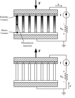
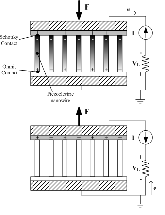
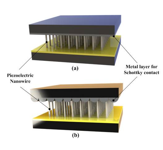
 Schematic view of typical Vertical nanowire Integrated Nanogenerator, (a) with full contact, and (b) with partial contact. Note that the grating on the counter electrode is important in the latter case.
VING is a 3-dimensional configuration consisting of a stack of 3 layers in general, which are the base electrode, the vertically grown piezoelectric nanostructure and the counter electrode. The piezoelectric nanostructure is usually grown from the base electrode by various synthesizing techniques, which are then integrated with the counter electrode in full or partial mechanical contact with its tip.
After Professor Zhong Lin Wang of the Georgia Institute of Technology has introduced a basic configuration of VING in 2006 where he used a tip of atomic force microscope (AFM) to induce the deformation of a single vertical ZnO nanowire, the first development of VING is followed in 2007.[3] The first VING utilizes the counter electrode with the periodic surface grating resembling the arrays of AFM tip as a moving electrode. Since the counter electrode is not in full contact with the tips of the piezoelectric nanowire, its motion in-plane or out-of-plane occurred by the external vibration induces the deformation of the piezoelectric nanostructure, leading to the generation of the electrical potential distribution inside each individual nanowire. It should be noted that the counter electrode is coated with the metal forming the schottky contact with the tip of the nanowire, where only the compressed portion of piezoelectric nanowire would allow the accumulated electrons pass through the barrier between its tip and the counter electrode, in case of n-type nanowire. The switch-on and –off characteristic of this configuration shows its capability of generating direct current generation without any requirement for the external rectifier.
In VING with partial contact, the geometry of the counter electrode plays an important role. The flat counter electrode would not induce the sufficient deformation of the piezoelectric nanostructures, especially when the counter electrode moves by in-plane mode. After the basic geometry resembling the array of AFM tips, a few other approaches have been followed for facile development of the counter electrode. Professor Zhong Lin Wang’s group have generated counter electrode composed of ZnO nanorods utilizing the similar technique used for synthesizing ZnO nanowire array. Professor Sang-Woo Kim's group of Sungkyunkwan University (SKKU) and Dr. Jae-Young Choi's group of Samsung Advanced Institute of Technology (SAIT) in South Korea introduced bowl-shaped transparent counter electrode by combining anodized aluminum and the electroplating technology.[4] They also have developed the other type of the counter electrode by using networked single-walled carbon-nanotube (SWNT) on the flexible substrate, which is not only effective for energy conversion but also transparent.[5]
The other type of VING has been also suggested. While it shares the identical geometric configuration with the aforementioned, such a VING has full mechanical contact between the tips of the nanowires and the counter electrode.[6] This configuration is effective for application where the force is exerted in the vertical direction (toward the c axis of the piezoelectric nanowire), and it generates alternating current (AC) unlike VINGs with partial contact.
Lateral nanowire Integrated Nanogenerator (LING)
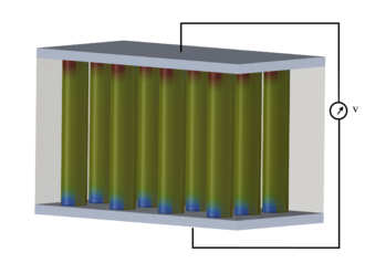
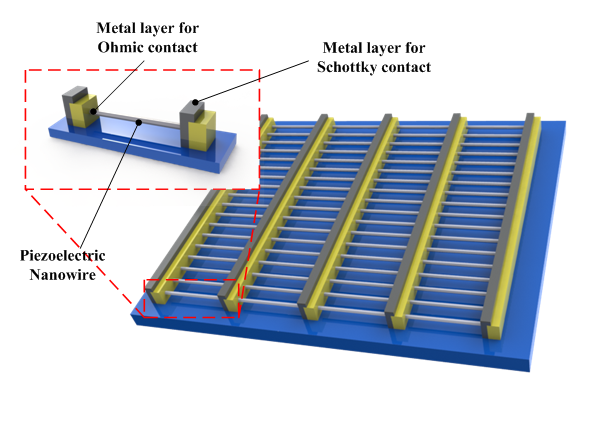
 Schematic view of typical Lateral nanowire Integrated Nanogenerator
LING is a 2-dimensional configuration consisting of three parts: the base electrode, the laterally grown piezoelectric nanostructure and the metal electrode for schottky contact. In most of cases, the thickness of the substrate film is much thicker than the diameter of the piezoelectric nanostructure, so the individual nanostructure is subjected to the pure tensile strain.
LING is an expansion of single wire generator (SWG), where a laterally aligned nanowire is integrated on the flexible substrate. SWG is rather a scientific configuration used for verifying the capability of electrical energy generation of a piezoelectric material and is widely adopted in the early stage of the development.
As of VINGs with full mechanical contact, LING generates AC electrical signal. The output voltage can be amplified by constructing an array of LING connected in series on the single substrate, leading the constructive addition of the output voltage. Such a configuration may lead to the practical application of LING for scavenging large-scale power, for example, wind or ocean waves.
Nanocomposite Electrical Generators (NEG)
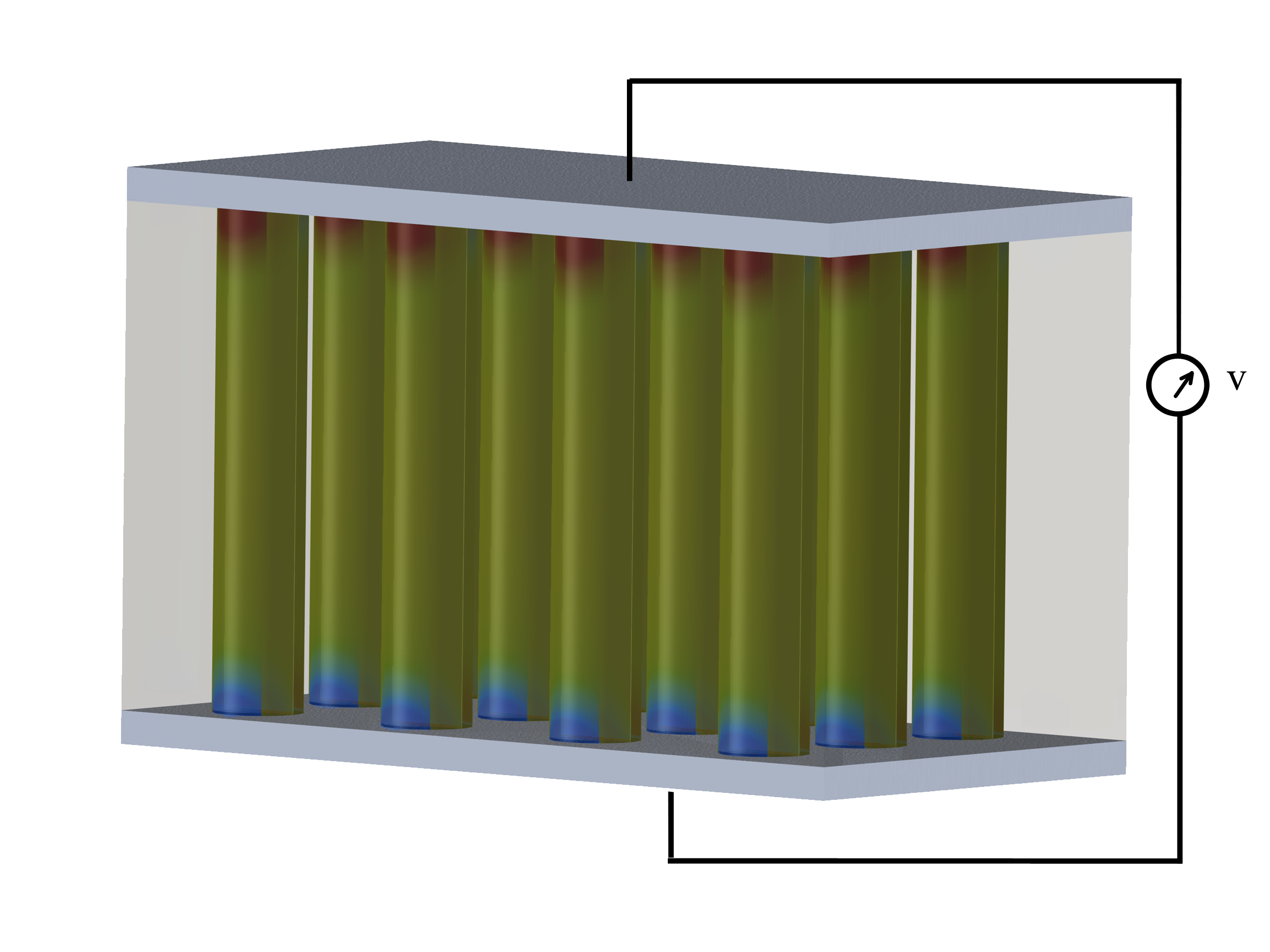
 Schematic view of typical Nanocomposite Electrical Generator
"NEG" is a 3-dimensional configuration consisting three main parts: the metal plate electrodes, the vertically grown piezoelectric nanostructure and the polymer matrix which fills in between in the piezoelectric nanostructure.
NEG was introduced by Momeni et al.[7] It was shown that NEG has a higher efficiency compared to original nanogenerator configuration which a ZnO nanowire will be bended by an AFM tip. It is also shown that it provides an energy source with higher sustainability.
Other type
The fabric-like geometrical configuration has been suggested by Professor Zhong Lin Wang in 2008. The piezoelectric nanowire is grown vertically on the two microfibers in its radial direction, and they are twined to form a nanogenerator.[8] One of the microfibers is coated with the metal to form a schottky contact, serving as the counter electrode of VINGs. As the movable microfiber is stretched, the deformation of the nanostructure occurs on the stationary microfiber, resulting in the voltage generation. Its working principle is identical to VINGs with partial mechanical contact, thus generating DC electrical signal.
Materials
Among various piezoelectric materials studied for the nanogenerator, many of the researches have been focused on the materials with wurtzite structure such as ZnO, CdS[9] and GaN.[10] The greatest advantage of theses material arises from the facile and cost-effective fabrication technique, hydrothermal synthesis. Since the hydrothermal synthesis can be conducted in a low temperature environment under 100°C in addition to vertical and crystalline growth , these materials can be integrated in various substrates with reduced concern for its physical characteristics such as a melting temperature.
Endeavors for enhancing the piezoelectricity of the individual nanowire also led to the development of other piezoelectric materials based on Wurtzite structure. Professor Zhong Lin Wang of Georgia Institute of Technology introduced p-type ZnO nanowire.[11] Unlike the n-type semiconductive nanostructure, the mobile particle in p-type is a hole, thus the schottky behavior is reversed from that of n-type case; the electrical signal is generated from the portion of the nanostructure where the holes are accumulated. It is experimentally proved that p-type ZnO nanowire can generate the output signal near 10 times that of n-type ZnO nanowire.
From the idea that the material with perovskite structure is known to have more effective piezoelectric characteristic compared to that with wurtzite structure, Barium titanate (BaTiO3) nanowire has been also studied by Professor Min-Feng Yu of University of Illinois at Urbana Champaign.[12] The output signal is found to be more than 16 time that from a similar ZnO nanowire.
Professor Liwei Lin of University of California at Berkeley has suggested that PVDF can be also applied to form a nanogenerator.[13] Being a polymer, PVDF utilizes a near-field electrospinning for its fabrication, which is rather a different technique compared to other materials. The nanofiber can be directly written on the substrate controlling the process, and this technique is expected to be applied for forming self-powered textile based on nanofiber.
Comparison of the reported materials by 2010 is given in the following table.
Material Type Geometry Output voltage Output power Synthesis Researched at ZnO(n-type) Wurtzite D: ~100 nm, L: 200~500 nm VP=~9 mV @ R=500MΩ ~0.5 pW per cycle (estimated) CVD, hydrothermal process Georgia Tech. ZnO(p-type) Wurtzite D: ~50 nm, L: ~600 nm VP=50~90 mV @ R=500MΩ 5~16.2 pW per cycle (calculated) CVD Georgia Tech. ZnO-ZnS Wurtzite (Heterostructure) Not stated VP=~6 mV @ R=500MΩ ~0.1 pW per cycle (calculated) Thermal evaporation and etching Georgia Tech. GaN Wurtzite D: 25~70 nm, L: 10~20 μm Vavg=~20 mV,Vmax=~0.35 V@ R=500MΩ ~0.8 pW per cycle (average, calculated) CVD Georgia Tech. CdS Wurtzite D: ~100 nm, L: 1 μm VP=~3 mV Not stated PVD, Hydrothermal Process Georgia Tech. BaTiO3 Pervoskite D: ~280 nm, L: ~15 μm VP=~25 mV @ R=100MΩ ~0.3 aJ per cycle (stated) High temperature chemical reaction UIUC PVDF Polymer D: 0.5~6.5 μm, L: 0.1~0.6 mm VP=5~30 mV 2.5 pW~90 pW per cycle (calculated) Electro spinning UC Berkely Applications
Nanogenerator is expected to be applied for various applications where the periodic kinetic energy exists, such as wind and ocean waves in a large scale to the muscle movement by the beat of a heart or inhalation of lung in a small scale. The further feasible applications are as follows.
Self-powered nano/micro devices
One of the feasible applications of nanogenerator is an independent or a supplementary energy source to nano/micro devices consuming relatively low amount of energy in a condition where the kinetic energy is supplied continuously. One of example has been introduced by Professor Zhong Lin Wang’s group in 2010 by the self-powered pH or UV sensor integrated VING with an output voltage of 20~40 mV onto the sensor.
Still, the converted electrical energy is relatively small for operating nano/micro devices; therefore the range of its application is still bounded as a supplementary energy source to the battery. The breakthrough is being sought by combining the nanogenerator with the other types of energy harvesting devices, such as solar cell or biochemical energy harvester.[14][15] This approach is expected to contribute to the development of the energy source suitable for the application where the independent operation is crucial, such as Smartdust.
Smart Wearable Systems
The outfit integrated or made of the textiles with the piezoelectric fiber is one of the feasible applications of the nanogenerator. The kinetic energy from the human body is converted to the electrical energy through the piezoelectric fibers, and it can be possibly applied to supply the portable electronic devices such as health-monitoring system attached with the Smart Wearable Systems. The nanogenerator such as VING can be also easily integrated in the shoe employing the walking motion of human body.
Another similar application is a power-generating artificial skin. Professor Zhong Lin Wang’s group has shown the possibility by generating AC voltage of up to 100 mV from the flexible SWG attached to the running hamster.[16]
Transparent and Flexible Devices
Some of the piezoelectric nanostructure can be formed in various kinds of substrates, such as flexible and transparent organic substrate. The research groups in SKKU (Professor Sang-Woo Kim’s group) and SAIT (Dr. Jae-Young Choi’s group) have developed the transparent and flexible nanogenerator which can be possibly used for self-powered tactile sensor and anticipated that the development may be extended to the energy-efficient touch screen devices. Their research focus is being extended to enhance the transparency of the device and the cost-effectiveness by substituting Indium-Tin-Oxide (ITO) electrode with a graphene layer.[17]
Implantable Telemetric Energy Receiver
The nanogenerator based on ZnO nanowire can be applied for implantable devices since ZnO not only is bio-compatible but also can be synthesized upon the organic substrate, rendering the nanogenerator bio-compatible in overall. The implantable device integrated with the nanogenerator can be operated by receiving the external ultrasonic vibration outside the human body, which is converted to the electrical energy by the piezoelectric nanostructure.
See also
- Battery (electricity)
- Electrical generator
- Energy harvesting
- Microelectromechanical Systems
- Micropower
- Nanoelectromechanical systems
- Piezoelectricity
- Smartdust
- Smart Wearable Systems
References
- ^ [1] Zhong Lin Wang and Jinhui Song, "Piezoelectric Nanogenerators Based on Zinc Oxide Nanowire Arrays," Science 312, 242
- ^ [2] Zhong Lin Wang, Xudong Wang, Jinhui Song, Jin Liu, and Yifan Gao, "Piezoelectric Nanogenerators for Self-Powered Nanodevices," IEEE Pervasive Computing, Vol. 7, No. 1, pp. 49-55
- ^ [3] Xudong Wang, Jinhui Song, Jin Liu, Zhong Lin Wang, "Direct-Current Nanogenerator Driven by Ultrasonic Waves," Science 316, 102, pp. 102-105
- ^ Min-Yeol Choi et. al, "Mechanically Powered Transparent Flexible Charge-Generating Nanodevices with Piezoelectric ZnO Nanorods," Adv. Mater. 2009, 21, pp. 2185–2189
- ^ Dukhyun Choi et. al, "Nanoscale Networked Single-Walled Carbon-Nanotube Electrodes for Transparent Flexible Nanogenerators," J. Phys. Chem. C 2010, 114, pp. 1379–1384
- ^ [4] Sheng Xu, Yong Qin, Chen Xu, Yaguang Wei, Rusen Yang and Zhong Lin Wang, "Self-powered nanowire devices," Nature Nanotechnology, Vol. 5, 2010, pp. 366-373
- ^ [5] Momeni, K., G.M. Odegard, and R.S. Yassar, Nanocomposite electrical generator based on piezoelectric zinc oxide nanowires. Journal of Applied Physics, 2010. 108(11): p. 114303-7
- ^ [6] Yong Qin, Xudong Wang & Zhong Lin Wang, "Microfibre–nanowire hybrid structure for energy scavenging," Nature, Vol. 45, 2008, pp. 809-813
- ^ Yi-Feng Lin, Jinhui Song, Yong Ding, Shih-Yuan Lu and Zhong Lin Wang, "Piezoelectric nanogenerator using CdS nanowires," Applied Physics Letter, 92, 2008, 022105
- ^ [7] Chi-Te Huang et. al, "GaN Nanowire Arrays for High-Output Nanogenerators," J. AM. CHEM. SOC. 2010, 132, pp. 4766–4771
- ^ [8] Ming-Pei Lu et. al, "Piezoelectric Nanogenerator Using p-Type ZnO Nanowire Arrays," Nano Lett., Vol. 9, No. 3, 2009, pp. 1223-1227
- ^ [9] Zhaoyu Wang, Jie Hu, Abhijit P. Suryavanshi, Kyungsuk Yum, and Min-Feng Yu, "Voltage Generation from Individual BaTiO3 Nanowires under Periodic Tensile Mechanical Load," Nano Lett., Vol. 7, No. 10, 2007, pp. 2966-2969
- ^ Chieh Chang, Van H. Tran, Junbo Wang, Yii-Kuen Fuh, and Liwei Lin, "Direct-Write Piezoelectric Polymeric Nanogenerator with High Energy Conversion Efficiency," Nano Lett. 2010, 10, pp. 726-731
- ^ [10] Chen Xu, Xudong Wang, and Zhong Lin Wang, "Nanowire Structured Hybrid Cell for Concurrently Scavenging Solar and Mechanical Energies," J. Am. Chem. Soc. 2009, 131, pp. 5866–5872
- ^ [11] Benjamin J. Hansen, Ying Liu, Rusen Yang, and Zhong Lin Wang, "Hybrid Nanogenerator for Concurrently Harvesting Biomechanical and Biochemical Energy," ACS Nano, Vol. 4, No. 7, 2010, pp.3647-3652
- ^ [12] Rusen Yang, Yong Qin, Cheng Li, Guang Zhu, and Zhong Lin Wang, "Converting Biomechanical Energy into Electricity by a Muscle-Movement-Driven Nanogenerator," Nano Letters, Vol. 9, No. 3, 2009, pp.1201-1205
- ^ Dukhyun Choi et. al, "Fully Rollable Transparent Nanogenerators Based on Graphene Electrodes," Adv. Mater. 2010, 22, pp. 2187–2192
External links
- Professor Z.L. Wang’s Nano Research Group at Georgia Institute of Technology
- Nano Electronic Science & Engineering Laboratory (NESEL) at Sungkyunkwan University (SKKU)
- Laboratory for Nanoscale Mechanics and Physics at University of Illinois, Urbana-Champaign
- LINLAB at University of California, Berkeley
- Samsung Advanced Institute of Technology
Categories:

Wikimedia Foundation. 2010.