- Flying wing
-
For the Canadian football position, see Flying wing (football).
Flying wing 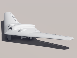
Graphic rendering A flying wing is a tailless fixed-wing aircraft which has no definite fuselage, with most of the crew, payload and equipment being housed inside the main wing structure.[1]
A flying wing may have various small protuberances such as pods, nacelles, blisters, booms, vertical stabilizers (tail fins), or undercarriage. Some aircraft have no fuselage but do have a separate horizontal stabilizer surface mounted on one or more booms; these are also commonly referred to as flying wings, although this is not strictly correct. An example of such a design is the Northrop X216H.[2]
Contents
History
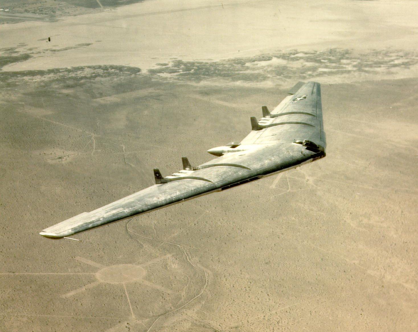
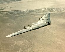 Northrop YB-49 flying wing
Tailless aircraft have been experimented with since the earliest attempts to fly. But it was not until the deep-chord monoplane wing became practicable after World War I that the opportunity to discard any form of fuselage arose and the true flying wing could be realised.
Hugo Junkers patented a wing-only air transport concept in 1910. He saw it as a natural solution to the problem of building an airliner large enough to carry a reasonable passenger load and enough fuel to cross the Atlantic in regular service. He believed that the flying wing's potentially large internal volume and low drag made it an obvious design for this role. In 1919 he started work on his "Giant" JG1 design, intended to seat passengers within thick wings, but two years later the Allied Aeronautical Commission of Control ordered the incomplete JG1 destroyed for exceeding post-war size limits on German aircraft. Junkers conceived futuristic flying wings for up to 1,000 passengers; the nearest this came to realization was in the 1931 Junkers G-38 34-seater Grossflugzeug airliner which featured a large thick-chord wing providing space for fuel, engines and two passenger cabins. However, it still required a short fuselage to house the crew and additional passengers.
The flying wing configuration was studied extensively in the 1930s and 1940s, notably by Jack Northrop and Cheston L. Eshelman in the United States, and Alexander Lippisch and the Horten brothers in Germany.
Soviet designers such as Boris Ivanovich Cheranovsky started research independently and in secret under Stalin after the 1920s.[3] With significant breakthrough in materials and construction methods, aircraft such as the BICh-3,[4] BICh-14, BICh-7A and so on became possible. Men like Chizhevskij and Antonov also came into the spotlight of the communist party by designing aircraft such as the tail-less BOK-5[5] (Chizhevskij) and OKA-33[6] (the first ever built by Antonov) which were designated as "motorized gliders" due to their similarity to popular gliders of the time. The BICh-11[7] by Cheranovsky in 1932 was competing with the Horten brothers H1 (and Adolf Galland) at the Ninth Glider Competitions in 1933, but did not demonstrate in the 1936 summer Olympics in Berlin. The BICh-26[8] was one of the first attempts at a supersonic jet flying-wing aircraft, ahead of its time in 1948[9] the airplane was not accepted by the military and the design died with Cheranovsky.
Early examples of true flying wings include:
- The Soviet Boris Ivanovich Cheranovsky built and tested tailless flying wings, from 1924 gliders, eventually also powered BICh-3.
- The French Charles Fauvel designed the AV3 glider, successfully flown in 1933,[10] featuring a self-stabilizing airfoil on a straight wing.[citation needed]
- The German Horten H1 glider flown with partial success in 1933, and the subsequent H2 flown successfully in both glider and powered variants.[11]
- The American Freel Flying Wing glider flown in 1937.[citation needed]
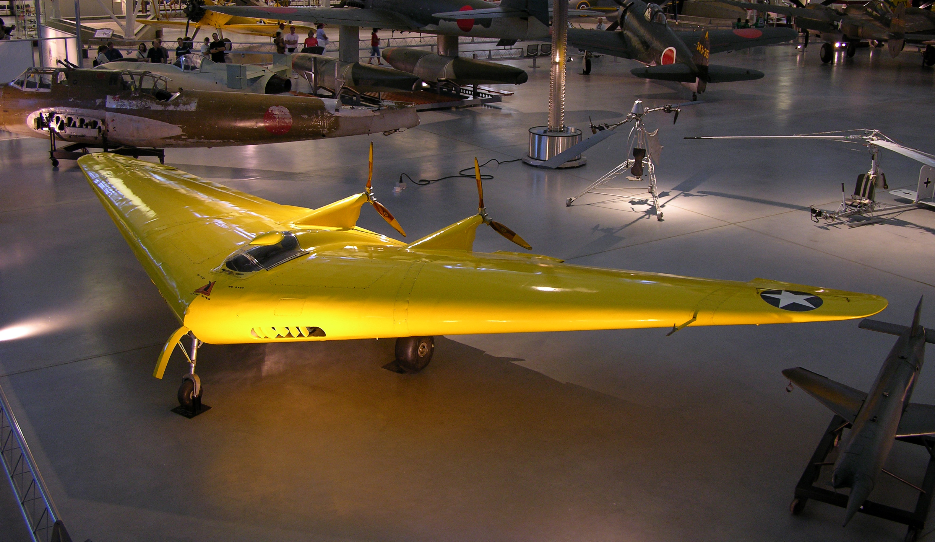
- The American Northrop N-1M of 1940.[12]
- The American Northrop N-9M of 1942.
- The American Northrop YB-35 of 1946.
- The American Northrop YB-49 of 1947.
- The British Armstrong Whitworth A.W.52G of 1944, a glider test bed[13] for the later Armstrong Whitworth A.W.52 jet-powered version.[14]
- The German Horten Ho 229 of 1945 - the world's first twin jet engine pure flying wing
Several late-war German military designs were based on the flying wing concept (or variations of it) as a proposed solution to extend the range of the otherwise very short-range jet engined aircraft. Most famous of these would be the Horten Ho 229 fighter. This aircraft, first flown in 1944, combined a flying wing, or Nurflügel, design with twin jet engines. The surviving prototype remains in storage at the Smithsonian Institution in an unrestored state.
After the war, a number of experimental designs were based on the flying wing concept, but the known difficulties remained intractable. Some general interest continued until the early 1950s, when the concept was proposed as a design solution for long range bombers. Such trends culminated in the Northrop YB-35 and YB-49, which did not enter production. Those designs did not necessarily offer a great advantage in range and presented a number of technical problems, leading to the adoption of "conventional" solutions like the Convair B-36 and the B-52 Stratofortress. Early designs of the Avro Vulcan by Roy Chadwick also explored flying wing designs.
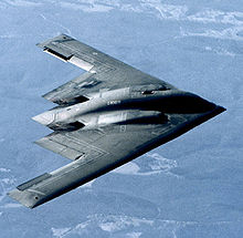
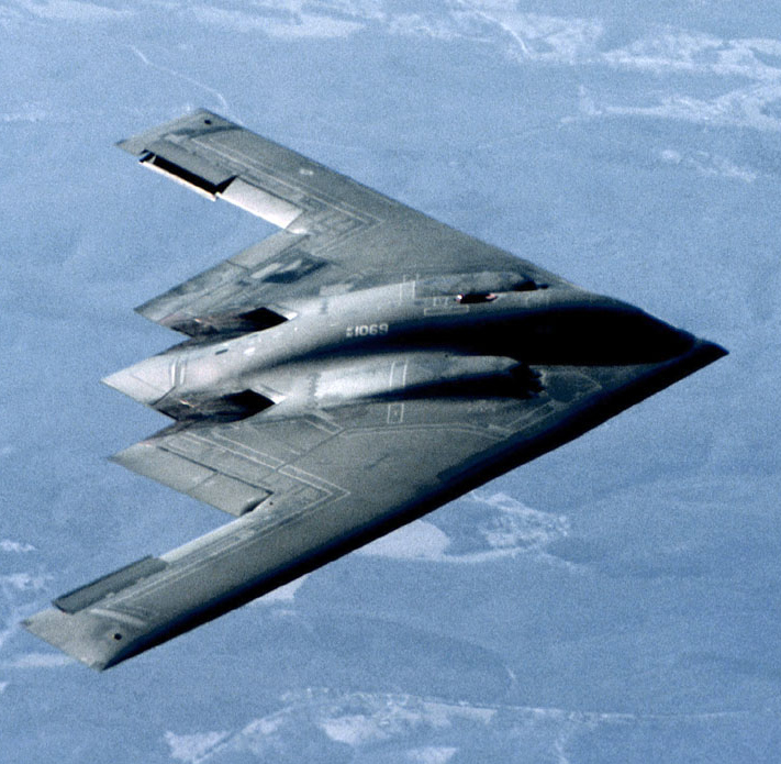
Interest in flying wings was renewed in the 1980s due to their potentially low radar reflection cross-sections. Stealth technology relies on shapes which only reflect radar waves in certain directions, thus making the aircraft hard to detect unless the radar receiver is at a specific position relative to the aircraft - a position that changes continuously as the aircraft moves. This approach eventually led to the Northrop B-2 Spirit stealth bomber. In this case the aerodynamic advantages of the flying wing are not the primary needs. However, modern computer-controlled fly-by-wire systems allowed for many of the aerodynamic drawbacks of the flying wing to be minimised, making for an efficient and stable long-range bomber.
Due to the practical need for a deep wing, the flying wing concept is most practical for designs in the slow-to-medium speed range, and there has been continual interest in using it as a tactical airlifter design. Boeing continues to work on paper projects for a Blended Wing Body Lockheed C-130 Hercules-sized transport with better range and about 1/3 more load, while maintaining the same size characteristics. A number of companies, including Boeing, McDonnell Douglas and de Havilland, did considerable design work on flying-wing airliners, but to date none have entered production.
Design issues

A clean flying wing is theoretically the most aerodynamically efficient (lowest drag) design configuration for a fixed wing aircraft. It also offers high structural efficiency for a given wing depth, leading to light weight and high fuel efficiency.
Because it lacks conventional stabilizing surfaces or the associated control surfaces, in its purest form the flying wing suffers from the inherent disadvantages of being unstable and difficult to control. These compromises are difficult to reconcile, and efforts to do so can reduce or even negate the expected advantages of the flying wing design, such as reductions in weight and drag. Moreover, solutions may produce a final design that is still too unsafe for certain uses, such as commercial aviation.
Further difficulties arise from the problem of fitting the pilot, engines, flight equipment and payload all within the depth of the wing section. A wing that is made deep enough to contain all these elements will have an increased frontal area, when compared to a conventional wing and fuselage, which in turn results in higher drag and thus slower speed than a conventional design. Typically the solution adopted in this case is to keep the wing reasonably thin, and the aircraft is then fitted with an assortment of blisters, pods, nacelles, fins and so forth to accommodate all the needs of a practical aircraft.
Other known problems with the flying wing design relate to pitch and yaw. Pitch issues are discussed in the article on tailless aircraft. The problems of yaw are discussed below.
Directional stability
For any aircraft to fly without constant correction it must have directional stability in yaw.
Flying wings lack the long fuselage which provides a convenient attachment point for an efficient vertical stabilizer or fin. The fin must attach directly on to the rear part of the wing, giving a small moment arm from the aerodynamic center, which in turn means that to be effective the fin area must be large. This large fin has weight and drag penalties, and can negate the advantages of the flying wing. The problem can be minimized by increasing the leading edge sweepback, as for example in a low-aspect-ratio delta wing, but most flying wings have gentler sweepback and consequently have, at best, marginal stability. In the so called ruptured duck[citation needed] configuration, the wing tip sections are angled sharply downwards (anhedral), increasing the area at the rear of the aircraft when viewed from the side.
Yaw control
In most flying wing designs, the stabilizing fins are so far forward that any control rudders mounted on them have little effect, thus alternative means for yaw control must be provided. The only practical solution is differential drag: the drag near one wing tip is artificially increased, causing the aircraft to yaw in the direction of that wing. Typical methods include:
- Split ailerons. The top surface moves up while the lower surface moves down, to create an air brake effect.
- Spoilers. A spoiler surface in the upper wing skin is raised, to disrupt the airflow and increase drag. This effect is generally accompanied by a loss of lift, which must be compensated for either by the pilot or by complex design features.
- Spoilerons. An upper surface spoiler which also acts to reduce lift (equivalent to deflecting an aileron upwards), so causing the aircraft to bank in the direction of the turn - the angle of roll causes the wing lift to act in the direction of turn, reducing the amount of drag required to turn the aircraft's longitudinal axis.
A consequence of the differential drag method is that if the aircraft manoeuvers frequently then it will frequently create drag. So flying wings are at their best when cruising in still air: in turbulent air or when changing course, the aircraft may be less efficient than a conventional design.
Borderline cases
Some aircraft have no fuselage but do have a horizontal stabilizer mounted on one or more booms. Strictly, these are not flying wings although they are usually referred to as such. An example is the Northrop X-216H, which has a tail stabilizer mounted on two tail booms but is regarded as Northrop's first flying wing type.
Many hang gliders and microlight aircraft are tailless. Although often referred to as flying wings, these types carry the pilot (and engine where fitted) below the wing structure rather than inside it, and so are not true flying wings.
An aircraft of sharply-swept delta planform and deep center section represents a borderline case between flying wing, blended wing body and/or lifting body configurations.
See also
- List of flying wing aircraft
- Blended wing body
- Delta wing
- Lifting body
- Oblique flying wing
- Vincent Burnelli
- Alsomitra
References
- ^ Crane, Dale: Dictionary of Aeronautical Terms, third edition, page 224. Aviation Supplies & Academics, 1997. ISBN 1-56027-287-2
- ^ Aerofiles (undated). "Northrop, Northrop-Grumman, Norair". http://www.aerofiles.com/_north.html. Retrieved 2009-01-31.
- ^ http://www.century-of-flight.net/new%20site/frames/horten%20frame.htm
- ^ "History of aircraft construction in the USSR" by V.B.Shavrov, Vol.1 p.431 (with images)
- ^ BOK-5, V.A.Chizhevskij
- ^ "History of aircraft construction in the USSR" by V.B.Shavrov, Vol.1 p.547-548
- ^ "Rocket fighter" by William Green, p.39-41
- ^ "History of aircraft construction in the USSR" by V.B.Shavrov, Vol.2 p.114
- ^ Gunston, Bill. “The Osprey Encyclopaedia of Russian Aircraft 1875–1995”. London, Osprey. 1995.
- ^ Pelletier Air Enthusiast July–August 1996, p.15.
- ^ U. S. NAVAL TECHNICALT MISSION IN EUROPE. "TECHNICAL REPORT NO. 76-45 ON. HORTEN TAILLESS AIRCRAFT" (PDF). Central Air Documents Office. p. 5. http://www.dtic.mil/cgi-bin/GetTRDoc?Location=U2&doc=GetTRDoc.pdf&AD=ADA800146. Retrieved 18 July 2010. "Hor ten. H-II Both glider and powered version - (see figures 19 and 20)"
- ^ Gunston 1996, p. 26.
- ^ "The A.W. Flying Wing" (Magazine). Flight. 9. http://www.flightglobal.com/pdfarchive/view/1946/1946%20-%200902.html. Retrieved 18 July 2010.
- ^ "Twin-jet A.W.52" (Magazine). Flight. 19. http://www.flightglobal.com/pdfarchive/view/1946/1946%20-%202270%20-%200296.html. Retrieved 18 July 2010.
- Gunston, Bill (1996). "Beyond the Frontiers: Northrop's Flying Wings". Wings of Fame (London: Aerospace Publishing) (Volume 2): pp. 24–37. ISBN 1 874023 69 7. ISSN 1361-2034.
- Kohn, Leo J. The Flying Wings of Northrop (1974) Milwaukee, WI: Aviation Publications ISBN 0-87994-031-X
- Maloney, Edward T. Northrop Flying Wings (1975) Buena Park, CA: Planes Of Fame Publishers ISBN 0-915464-00-4
- Pelletier, Alain J. "Towards the Ideal Aircraft? The Life and Times of the Flying Wing Part One: Beginnings to 1945". Air Enthusiast (64, July–August 1994): pp. 2–17. ISSN 0143-5450.
External links
- History of the Flying Wing at Century of Flight.
- The Nurflügel page
- Flight to the Future by Joe Mizrahi, Wings, April 1999, Vol. 29, No. 2
- Glen Edwards and the Flying Wing
- Flying Wings Are Coming, March 1942
Lists relating to aviation General Aircraft (manufacturers) · Aircraft engines (manufacturers) · Airlines (defunct) · Airports · Civil authorities · Museums · Registration prefixes · Rotorcraft (manufacturers) · TimelineMilitary Accidents/incidents Records Categories:- Flying wing aircraft
- Wing configurations
- Aircraft wing design

Wikimedia Foundation. 2010.