Controlled NOT gate

Controlled NOT gate
The classical analog of the CNOT gate is the XOR gate.
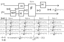
How CNOT gate can be used (with Hadamard gates) in a computation.
It is that can represent CNOT gate.
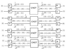
Answer on output depending of input and CNOT function.
first qubit flips only if second qubit is 1.

The Controlled NOT gate (also C-NOT or CNOT) is a quantum gate that is an essential component in the construction of a quantum computer. It can be used to disentangle EPR states. Specifically, any quantum circuit can be simulated to an arbitrary degree of accuracy using a combination of CNOT gates and single qubit rotations.

Contents

Operation

The CNOT gate flips the second qubit (the target qubit) if and only if the first qubit (the control qubit) is 1.

Before After
Control Target Control Target
0 0 0 0
0 1 0 1
1 0 1 1
1 1 1 0

The resulting value of the second qubit corresponds to the result of a classical XOR gate.

The CNOT gate can be represented by the matrix:

 \operatorname{CNOT} =  \begin{bmatrix} 1 & 0 & 0 & 0 \\ 0 & 1 & 0 & 0 \\ 0 & 0 & 0 & 1 \\  0 & 0 & 1 & 0 \end{bmatrix}.

The first experimental realization of a CNOT gate was accomplished in 1995. Here, a single Beryllium ion in a trap was used. The two qubits were encoded into an optical state and into the vibrational state of the ion within the trap. At the time of the experiment, the reliability of the CNOT-operation was measured to be on the order of 90%.

In addition to a regular Controlled NOT gate, one could construct a Function-Controlled NOT gate, which accepts an arbitrary number n+1 of qubits as input, where n+1 is greater than or equal to 2 (a quantum register). This gate flips the last qubit of the register if and only if a built-in function, with the first n qubits as input, returns a 1. The Function-Controlled NOT gate is an essential element of the Deutsch-Jozsa algorithm. CNOT is also a kind of universal gate(in the classical sense of the word). It is easy to see that if the CONTROL is set to '1' the TARGET output is always NOT. So, a NOT GATE can be constructed using CNOT. Further, we can construct an AND GATE by using two CNOTs. Look at the table below

Before After
Control Target Control Target
0 0 0 0
0 1 0 1
1 0 1 1
1 1 1 0
Before After
Control Target Control Target
0 0 0 0
1 0 0 0
1 1 1 0
0 1 1 1

Proof of operation

Let \left\{ 
|0\rangle =\! \begin{bmatrix} 1 \\ 0 \end{bmatrix}, 
|1\rangle =\! \begin{bmatrix} 0 \\ 1 \end{bmatrix} 
\right\} be the orthonormal basis (using Bra-ket notation).

Let | \psi \rangle = a | 0 \rangle + b | 1 \rangle =\! \begin{bmatrix} a \\ b \end{bmatrix}.

Let | \phi \rangle = b | 0 \rangle + a | 1 \rangle =\! \begin{bmatrix} b \\ a \end{bmatrix} be the flip qubit of  | \psi \rangle.

Recall that |\alpha\rangle\!\otimes\!|\beta\rangle 
                  = |\alpha\rangle |\beta\rangle 
                  = |\alpha,\beta\rangle .

When control qubit is 0

First, we shall prove that 
\operatorname{CNOT}\ |0,\psi\rangle = |0,\psi\rangle
:

Before we compute, however, note that our specific definition of  \operatorname{CNOT}\ assumes an eigenbasis of

 |00\rangle = \begin{bmatrix} 1 \\ 0 \\ 0 \\ 0 \end{bmatrix}, |01\rangle = \begin{bmatrix} 0 \\ 1 \\ 0 \\ 0 \end{bmatrix} , |10\rangle = \begin{bmatrix} 0 \\ 0 \\ 1 \\ 0 \end{bmatrix}, |11\rangle = \begin{bmatrix} 0 \\ 0 \\ 0 \\ 1 \end{bmatrix}

Then, it's not difficult to verify that 
|0,\psi\rangle = a|0\rangle |0\rangle + b|0\rangle |1\rangle = \begin{bmatrix} a \\ b \\ 0 \\ 0 \end{bmatrix}

Then \operatorname{CNOT}\ |0,\psi\rangle = \begin{bmatrix} 1 & 0 & 0 & 0 \\ 0 & 1 & 0 & 0 \\ 0 & 0 & 0 & 1 \\ 0 & 0 & 1 & 0 \end{bmatrix} \begin{bmatrix} a \\ b \\ 0 \\ 0 \end{bmatrix} = \begin{bmatrix} a \\ b \\ 0 \\ 0 \end{bmatrix} = |0,\psi\rangle.

Therefore CNOT doesn't change the  |\psi\rangle qubit if the first qubit is 0.

When control qubit is 1

Now, we shall prove that  \operatorname{CNOT}\ |1,\psi\rangle = |1,\phi\rangle, which means that the CNOT gate flips the |\psi\rangle qubit.

Similarly to the first demonstration, we have  |1,\psi\rangle = \begin{bmatrix} 0 \\ 0 \\ a \\ b \end{bmatrix}.

Then  \operatorname{CNOT}\ |1,\psi\rangle = \begin{bmatrix} 1 & 0 & 0 & 0 \\ 0 & 1 & 0 & 0 \\ 0 & 0 & 0 & 1 \\ 0 & 0 & 1 & 0 \end{bmatrix} \begin{bmatrix} 0 \\ 0 \\ a \\ b \end{bmatrix} = a \begin{bmatrix} 0 \\ 0 \\ 0 \\ 1 \end{bmatrix} + b \begin{bmatrix} 0 \\ 0 \\ 1 \\ 0 \end{bmatrix}

As we can see that  |1,1\rangle = \begin{bmatrix} 0 \\ 0 \\ 0 \\ 1 \end{bmatrix} and  |1,0\rangle = \begin{bmatrix} 0 \\ 0 \\ 1 \\ 0 \end{bmatrix}, using these on the equation above gives


\begin{align}
\operatorname{CNOT}\ |1,\psi\rangle 
     & = a |1,1\rangle + b |1,0\rangle \\
     & = |1\rangle \left( a |1\rangle  + b |0\rangle \right) \\
     & = |1,\phi\rangle \\
\end{align}

Therefore the CNOT gate flips the |\psi\rangle qubit into |\phi\rangle if the control qubit is set to 1. A simple way to observe this is to multiply the CNOT matrix by a column vector, noticing that the operation on the first bit is identity, and a NOT gate on the second bit.

References

  • Nielsen, Michael A. & Chuang, Isaac L. (2000). Quantum Computation and Quantum Information. Cambridge University Press. ISBN 0-521-63235-8. 

Wikimedia Foundation. 2010.

Игры ⚽ Поможем написать реферат

Look at other dictionaries:

  • Quantum gate — A quantum gate or quantum logic gate is a basic quantum circuit operating on a small number of qubits. They are the analogues for quantum computers to classical logic gates for conventional digital computers. Quantum logic gates are reversible,… …   Wikipedia

  • Toffoli gate — In computer science, the Toffoli gate, invented by Tommaso Toffoli, is a universal reversible logic gate, which means that any reversible circuit can be constructed from Toffoli gates. It is also known as the controlled controlled not gate, which …   Wikipedia

  • Fredkin gate — The Fredkin gate is computational circuit suitable for reversible computing, invented by Ed Fredkin. It is universal , which means that any logical or arithmetic operation can be constructed entirely of Fredkin gates.The basic Fredkin gate is a… …   Wikipedia

  • Gate turn-off thyristor — For other uses of the word, see GTO (disambiguation). GTO thyristor symbol A gate turn off thyristor (GTO) is a special type of thyristor, a high power semiconductor device. GTOs, as opposed to normal thyristors, are fully controllable switches… …   Wikipedia

  • C-ROT gate — The C ROT gate (controlled Rabi rotation) is equivalent to a C NOT gate except for a pi=2 rotation of the nuclear spin around the z axis [P. Chen, C. Piermarocchi, and L. J. Sham, Phys. Rev. Lett. 87, 067401 (2001),… …   Wikipedia

  • Noise gate — A Noise Gate or gate is an electronic device or software that is used to control the volume of an audio signal. In its most simple form, a noise gate allows a signal to pass through only when it is above a set threshold: the gate is open . If the …   Wikipedia

  • CV/Gate — (an abbreviation of Control Voltage/Gate) is an analog method of controlling synthesizers, drum machines and other similar equipment with external sequencers. The Control Voltage typically controls pitch and the Gate signal controls note on/off.… …   Wikipedia

  • Silicon-controlled rectifier — A silicon controlled rectifier (or semiconductor controlled rectifier) is a four layer solid state device that controls current. The name silicon controlled rectifier or SCR is General Electric s trade name for a type of thyristor. The SCR was… …   Wikipedia

  • Golden Gate Bridge — Carries 6 lanes of …   Wikipedia

  • The Death Gate Cycle — is a seven part series (heptalogy) of fantasy novels written by Margaret Weis and Tracy Hickman. The main conflict is between two powerful races, the Sartan and the Patryns, which branched off from humans following a nuclear/anti matter holocaust …   Wikipedia

Share the article and excerpts

Direct link
Do a right-click on the link above
and select “Copy Link”