- Dual-modulus prescaler
-
A dual modulus prescaler is an electronic circuit used in high-frequency synthesizer designs to overcome the problem of generating narrowly-spaced frequencies that are nevertheless too high to be passed directly through the feedback loop of the system. The modulus of a prescaler is its frequency divisor. A dual-modulus prescaler has two separate frequency divisors, usually M and M+1.
Contents
The problem
A frequency synthesizer produces an output frequency, f, which divided by the modulus is the reference frequency, fr:

The modulus, N, is generally restricted to integral values, as the comparator will match when the waveform is in phase. Typically, the possible frequency multiples will be the channels for which the radio equipment is designed for, so fr will usually be equal to the channel spacing. For example, on narrow-band radiotelephones, a channel spacing of 12.5 kHz is typical.
Suppose that the programmable divider, using N, is only able to operate at a maximum clock frequency of 10 MHz, but the output f is in the hundreds of MHz range; . Interposing a fixed prescaler, which can operate at this frequency range, with a value M of say, 40, drops the output frequency into the operating range of the programmable divider. However, a factor of 40 has been introduced into the equation, so the output frequency is now:
fo = 40Nfr
If fr remains at 12.5 kHz, only every 40th channel can be obtained. Alternatively, if fr is reduced by a factor of 40 to compensate, it becomes 312.5 Hz, which is much too low to give good filtering and lock performance characteristics. It also means that programming the divider becomes more complex, as the modulus needs to be verified so that only those that give true channels are used, not every 1/40th of a channel that is available.
The solution
The solution is the dual modulus prescaler. The main divider is split into two parts, the main part N and an additional divider A which is strictly lesser than N. Both dividers are clocked from the output of the dual-modulus prescaler, but only the output of the N divider is fed back to the comparator. Initially, the prescaler is set to divide by M + 1. Both N and A count down until A reaches zero, at which point the prescaler is switched to a division ratio of M. At this point, the divider N has completed A counts. Counting continues until N reaches zero, which is an additional N - A counts. At this point the cycle repeats.
![\begin{align}
&f_o = f_r\left[{M(N-A) + (M+1)A}\right]\\
\Rightarrow &f_o = f_r\left(MN+A\right)
\end{align}](0/9b0c2bcae74dbcbdd71d958e940876a8.png)
So while we still have a factor of M being multiplied by N, we can add an additional count, A, which effectively gives us a divider with a fractional part. Only the prescaler needs to be constructed from high-speed parts, and the reference frequency can remain equal to the desired output frequency spacing.
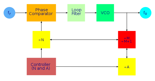
The diagram below shows the elements and arrangement of a frequency synthesizer with dual-modulus prescaler. (Compare with diagram on main synthesizer page).
One can compute A and N from the formulae:

where V is the combined division ratio V = MN+A. For this to work properly, A must be strictly less than M, as well as less than or equal to N. These restrictions on values of A imply that you can't get every division ratio V. If V falls below M(M - 1), some channels will be missing.
Example
 Dual modulus prescaler waveform with a 10 microsecond scale.
 Dual modulus prescaler waveform with a 20 nanosecond scale.
Today, most dual-modulus prescalers exist inside of PLL chips, making it impossible to probe actual signals during operation. The first dual-modulus prescalers were discrete ECL devices, separate from the PLL chips. Here is an example of a dual-modulus prescaler in use. This circuit happens to use a Motorola MC145158 with a Fujitsu MB-501 dual-modulus prescaler operating in the 128/129 mode. The PLL is locked at 917.94 MHz (fo) with a channel spacing frequency of 30 kHz (fr). The total integer count therefore is 30,598. Dividing this by 128 (M) yields a quotient of 239 with a remainder of 6, N and A respectively. The result of this frequency choice is that the prescaler spends most of its time counting at 128, and just a brief period at 129.
This is shown by the upper purple trace, the modulus control, A, counter output. These two screen captures differ only in the horizontal scale. The lower, yellow trace is the N counter output whose frequency corresponds to the channel spacing frequency of 30 kHz. The green trace is the output from the dual-modulus prescaler, which happens to correspond to 7.1714 MHz in the case that the prescaler is at 128 and 7.1158 when it is at 129. It is plainly obvious that the modulus control is low for precisely 6 cycles of the prescaler output. What is not obvious is the fact that the frequency changes by less than one percent between the two states of the modulus control. There will be cases where A = 0, resulting in the dual-modulus prescaler counting only by 128. This would happen at 906.24, 910.08, 913.92, 917.76, 921.60 MHz and so on.
See also
- pulse swallowing counter, pulse swallowing divider
Categories:- Digital circuits
- Communication circuits
- Telecommunications equipment


Wikimedia Foundation. 2010.