- Network analyzer (electrical)
-
Not to be confused with packet analyzer or telecom network protocol analyzer.
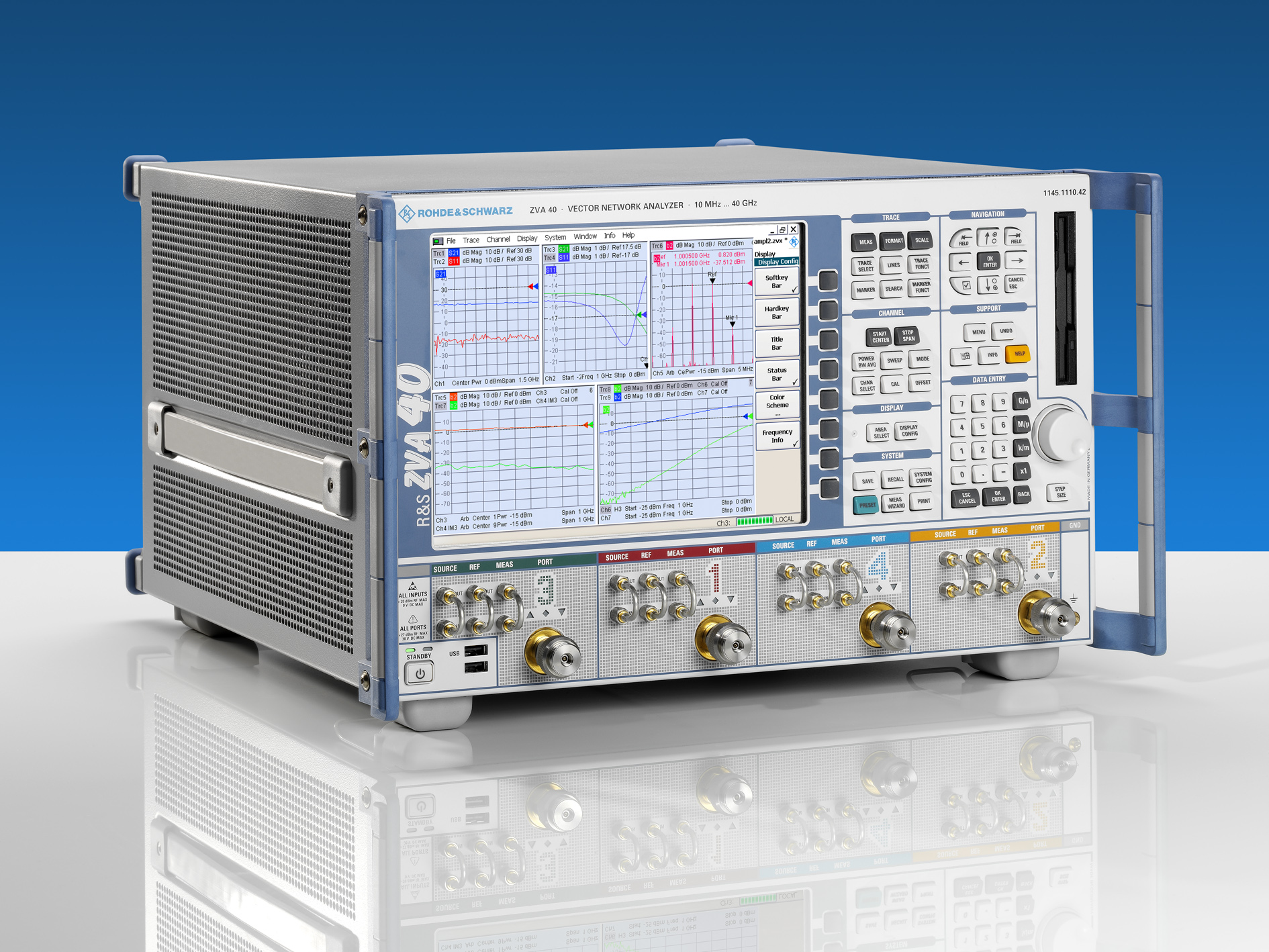
 ZVA40 vector network analyser from Rohde & Schwarz.
A network analyzer is an instrument that measures the network parameters of electrical networks. Today, network analyzers commonly measure s–parameters because reflection and transmission of electrical networks are easy to measure at high frequencies, but there are other network parameter sets such as y-parameters, z-parameters, and h-parameters. Network analyzers are often used to characterize two-port networks such as amplifiers and filters, but they can be used on networks with an arbitrary number of ports.
Contents
Overview

Network analyzers are used mostly at high frequencies; operating frequencies can range from 9 kHz to 110 GHz.[1] Special types of network analyzers can also cover lower frequency ranges down to 1 Hz. These network analyzers can be used for example for the stability analysis of open loops or for the measurement of audio and ultrasonic components.[2]
The two main types of network analyzers are
- Scalar Network Analyzer (SNA) — measures amplitude properties only
- Vector Network Analyzer (VNA) — measures both amplitude and phase properties
A VNA may also be called a gain-phase meter or an Automatic Network Analyzer. An SNA is functionally identical to a spectrum analyzer in combination with a tracking generator. As of 2007[update], VNAs are the most common type of network analyzers, and so references to an unqualified “network analyzer” most often mean a VNA. The three biggest VNA manufacturers are Agilent, Anritsu, and Rohde & Schwarz.
A new category of network analyzer is the Microwave Transition Analyzer (MTA) or Large Signal Network Analyzer (LSNA), which measure both amplitude and phase of the fundamental and harmonics. The MTA was commercialized before the LSNA, but was lacking some of the user-friendly calibration features now available with the LSNA.
Architecture
 The basic parts of a vector network analyzer
The basic architecture of a network analyzer involves a signal generator, a test set, and one or more receivers. In some setups, these units are distinct instruments.
See scattering parameters#Measurement of S-parameters.
Signal generator
The network analyzer needs a test signal, and a signal generator or signal source will provide one. Older network analyzers did not have their own signal generator, but had the ability to control a stand alone signal generator using, for example, a GPIB connection. Nearly all modern network analyzers have a built-in signal generator. High-performance network analyzers have two built-in sources. Two built-in sources are useful for applications such as mixer test, where one source provides the RF signal, another the LO, or amplifier intermodulation testing, where two tones are required for the test.
Test set
The test set takes the signal generator output and routes it to the device under test, and it routes the signal to be measured to the receivers.
It often splits off a reference channel for the incident wave. In a SNA, the reference channel may go to a diode detector (receiver) whose output is sent to the signal generator's automatic level control. The result is better control of the signal generator's output and better measurement accuracy. In a VNA, the reference channel goes to the receivers; it is needed to serve as a phase reference.
Directional coupler. Two resistor power divider.
Some microwave test sets include the front end mixers for the receivers (e.g., test sets for HP 8510).
The test sets may also contain directional couplers to measure reflected waves.
Transmission/reflection test set.
S-parameter test set.
Receiver
The receivers make the measurements. A network analyzer will have one or more receivers connected to its test ports. The reference test port is usually lableled R, and the primary test ports are A, B, C,.... Some analyzers will dedicate a separate receiver to each test port, but others share one or two receivers among the ports. The R receiver may be less sensitive than the receivers used on the test ports.
For the SNA, the receiver only measures the magnitude of the signal. A receiver can be a detector diode that operates at the test frequency. The simplest SNA will have a single test port, but more accurate measurements are made when a reference port is also used. The reference port will compensate for amplitude variations in the test signal at the measurement plane. It is possible to share a single detector and use it for both the reference port and the test port by making two measurement passes.
For the VNA, the receiver measures both the magnitude and the phase of the signal. It needs a reference channel (R) to determine the phase, so a VNA needs at least two receivers. The usual method down converts the reference and test channels to make the measurements at a lower frequency. The phase may be measured with a quadrature detector. A VNA requires at least two receivers, but some will have three or four receivers to permit simultaneous measurement of different parameters.
There are some VNA architectures (six-port) that infer phase and magnitude from just power measurements.
Calibration
The accuracy and repeatability of measurements can be improved with calibration. Calibration involves measuring known standards and using those measurements to compensate for systematic errors. After making these measurements, the network analyzer can compute some correction values to produce the expected answer. For answers that are supposed to be zero, the analyzer can subtract the residual. For non-zero values, the analyzer could calculate complex factors that will compensate for both phase and amplitude errors. Calibrations can be simple (such as compensating for transmission line length) or involved methods that compensate for losses, mismatches, and feedthroughs.
A network analyzer (or its test set) will have connectors on its front panel, but the measurements are seldom made at the front panel. Usually some test cables will go from the front panel to the device under test (DUT) such as a two-port filter or amplifier. The length of those cables will introduce a time delay and corresponding phase shift (affecting VNA measurements); the cables may also introduce some attenuation (affecting SNA and VNA measurements).
S-parameter measurements have a notion of a reference plane. The goal is to refer all measurements to the reference plane.
Using ideal shorts, opens, and loads makes calibration easy, but ideal standards are difficult to make. Modern network analyzers will account for the imperfections in the standards. (Agilent 2006)
Automated calibration fixtures
A calibration using a mechanical calibration kit may take a significant amount of time. Not only must the operator sweep through all the frequencies of interest, but the operator must also disconnect and reconnect the various standards. (Agilent 2003, p. 9) To avoid that work, network analyzers can employ automated calibration standards. (Agilent 2003) The operator connects one box to the network analyzer. The box has a set of standards inside and some switches that have already been characterized. The network analyzer can read the characterization and control the configuration using a digital bus such as USB.
AC power systems
From 1929 [3] to the late 1960s, large alternating current power systems were modelled and studied on AC network analyzers ( or Transient network analyzers). These were an outgrowth of the DC calculating boards used in the very earliest power system analysis. These systems were essentially models of the power system, with generators, transmission lines, and loads represented by miniature electrical components with scale values in proportion to the modeled system.[4] Model components were interconnected with flexible cords to represent the schematic of the modelled system. To reduce the size of the model components, the network analyzer was energized at a higher frequency than the 50 Hz or 60 Hz utility frequency, and model circuits were energized at relatively low voltages to allow for safe measurement with adequate precision. Typically, results accurate to around 2% of measurement could be obtained. [5]
AC network analyzers were much used for power flow studies, short circuit calculations, and system stability studies, but were ultimately replaced by numerical solutions running on digital computers. While the analyzers could provide real-time simulation of events, with no concerns about numeric stability of algorithms, the analyzers were costly, inflexible, and limited in the number of busses and lines that could be simmulated. [6] Since the multiple elements of the AC network analyzer formed a powerful analog computer, occasionally problems in physics and chemistry were modelled (by such researchers as Gabriel Kron of General Electric), during the period up to the late 1940s prior to the ready availability of general-purpose digital computers.[7]
See also
- Bode plotter
- Electrical measurements
- Scattering parameters
- Smith chart
Notes
- ^ Agilent - Network Analyzer products, as of 2 Jan 2007
- ^ OMICRON Lab Vector Network Analyzer products, as of 3 April 2008
- ^ Thomas Parke Hughes Networks of power: electrification in Western society, 1880-1930 JHU Press, 1993 ISBN 0801846145 page 376
- ^ Edward Wilson Kimbark , Power System Stability,Wiley-IEEE ,1948, ISBN 0780311353 page 64 and following
- ^ Institution of Engineering and Technology , Power System Protection, Volumes 1-4, 1995 ISBN 978-1-60119-889-1 pages 216-220
- ^ M.A. Laughton, D.F Warne (ed),Electrical Engineer's Reference Book (16th Edition), Elsevier, 2003 ISBN 978-1-60119-452-7 pages 368-369
- ^ http://www.metaphorik.de/12/tympasdalouka.pdf retrieved 2008 Jan 26
References
- Agilent (June 9, 2003), Electronic vs. Mechanical Calibration Kits: Calibration Methods and Accuracy, White Paper, Agilent Technologies, http://cp.literature.agilent.com/litweb/pdf/5988-9477EN.pdf
- Agilent (July 13, 2006), Specifying Calibration Standards for the Agilent 8510 Network Analyzer, Application Note 8510-5B, Agilent Technologies, http://cp.literature.agilent.com/litweb/pdf/5956-4352.pdf
External links
- Network Analyzer Basics (PDF, 5.69 MB), from Agilent
- Primer on Vector Network Analysis (PDF, 123 KB), from Anritsu
- Large-Signal Network Analysis (PDF, 3.73 MB), by Dr. Jan Verspecht
- Homebrew VNA by Paul Kiciak, N2PK
- Measuring Frequency Response (PDF, 961 KB), by Dr Ray Ridley
- RF network analyzer basics with additional pages for VNA, etc
Electrical and electronic measuring equipment Ammeter · Capacitance meter · Distortionmeter · Electric energy meter · LCR meter · Microwave power meter · Multimeter · Network analyzer · Ohmmeter · Oscilloscope · Psophometer · Q meter · Signal analyzer · Signal generator · Spectrum analyzer · Transistor tester · Tube tester · Wattmeter · Vectorscope · Video signal generator · Voltmeter · VU meter
Categories:- Radio electronics
- Electronic test equipment
- Measuring instruments
- Laboratory equipment
- Electrical engineering


Wikimedia Foundation. 2010.