- Meridian circle
-
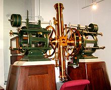
 Groombridge transit circle of 1806
The meridian circle, transit circle, or transit telescope is an instrument for observing the time of stars passing the meridian, at the same time measuring its angular distance from the zenith. The idea of having an instrument (quadrant) fixed in the plane of the meridian occurred even to the ancient astronomers and is mentioned by Ptolemy, but it was not carried into practice until Tycho Brahe constructed a large meridian quadrant.
They are a special purpose telescope mounted so as to allow it to be pointed only at objects in the sky crossing the local meridian, an event known as a transit. These telescopes rely on the rotation of the Earth to bring objects into their field of view and are fixed on a east-west axis.
Meridian circles have been used since the 18th century to accurately measure positions of stars in order to catalog them. This is done by measuring the instant when the star passes through the local meridian. Its altitude above the horizon is noted as well. Knowing one's geographic latitude and longitude these measurements can be used to derive the star's right ascension and declination.
Once good star catalogs were available a transit telescope could be used anywhere in the world to accurately measure local longitude and time by observing local meridian transit times of catalogue stars. Prior to the invention of the atomic clock this was the most reliable source of accurate time.
Contents
History
Antiquity
In the Almagest Ptolemy describes a meridian circle which consisted of a fixed graduated outer ring and a movable inner ring with tabs that used a shadow to set the Sun's position. It was mounted vertically and aligned with the meridian. The instrument was used to measure the altitude of the Sun at noon in order to determine the path of the ecliptic.[1]
17th century (1600s)
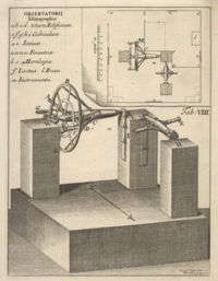 The world's first meridian circle from Ole Rømer's Observatorium Tusculanum
A meridian circle enabled the observer to determine simultaneously right ascension and declination, but it does not appear to have been much used for right ascension during the 17th century, the method of equal altitudes by portable quadrants or measures of the angular distance between stars with an astronomical sextant being preferred. These methods were very inconvenient and in 1690 Ole Rømer invented the transit instrument.
18th century (1700s)
The transit instrument consists of a horizontal axis in the direction east and west resting on firmly fixed supports, and having a telescope fixed at right angles to it, revolving freely in the plane of the meridian: At the same time Rømer invented the altitude and azimuth instrument for measuring vertical and horizontal angles, and in 1704 he combined a vertical circle with his transit instrument, so as to determine both co-ordinates at the same time.
This latter idea was, however, not adopted elsewhere although the transit instrument soon came into universal use (the first one at Greenwich was mounted in 1721), and the mural quadrant continued till the end of the century to be employed for determining declinations. The advantage of using a whole circle, as less liable to change its figure, and not requiring reversal in order to observe stars north of the zenith, was then again recognized by Jesse Ramsden, who also improved the method of reading off angles by means of a micrometer microscope as described below.
19th century (1800s)
 Meridian circle at the Kuffner observatory (Vienna, Austria)
The making of circles was shortly afterwards taken up by Edward Troughton, who in 1806 constructed the first modern transit circle for Groombridge's observatory at Blackheath, the Groombridge Transit Circle (a meridian transit circle). Troughton afterwards abandoned the idea, and designed the mural circle to take the place of the mural quadrant.
In the United Kingdom the transit instrument and mural circle continued till the middle of the 19th century to be the principal instrument in observatories, the first transit circle constructed there being that at Greenwich (mounted in 1850) but on the continent the transit circle superseded them from the years 1818-1819, when two circles by Johann Georg Repsold and by Reichenbach were mounted at Göttingen, and one by Reichenbach at Königsberg. The firm of Repsold and Sons was for a number of years eclipsed by that of Pistor and Martins in Berlin, who furnished various observatories with first-class instruments, but since the death of Martins the Repsolds have again taken the lead, and have of late years made many transit circles. The observatories of Harvard College (United States), Cambridge and Edinburgh have large circles by Troughton and Simms, who also made the Greenwich circle from the design of Airy.
20th Century (1900s)
 Chabot Space & Science Center's meridian transit telescope.
 The Ron Stone FASTT of the USN
A modern day example of this type of telescope is the 8 inch (~0.2m) Flagstaff Astrometric Scanning Transit Telescope (FASTT) at the USNO Flagstaff Station Observatory. [2] Modern meridian circles have typically switched to drift-scan with digital film, and are automated. The first automated instrument was the Carlsberg Automatic Meridian Circle, which came online in 1984.[3]
Structure
In the earliest transit instrument the telescope was not placed in the middle of the axis, but much nearer to one end, in order to prevent the axis from bending under the weight of the telescope. It is now always placed in the centre of the axis. The latter consists of one piece of brass or gun-metal with carefully turned cylindrical steel pivots at each end.
Several recent instruments have been made entirely of steel, which is much more rigid than brass. The centre of the axis is shaped like a cube, the sides of which form the basis of two cones which end in cylindrical parts. The pivots rest on V-shaped bearings, either let into the massive stone or brick piers which support the instrument or attached to metal frameworks bolted on the tops of the piers: In order to relieve the pivots from the weight of the instrument, which would soon destroy their figure, the cylindrical part of each end of the axis is supported by a hook supplied with friction rollers, and suspended from a lever supported by the pier and counterbalanced so as to leave only about 10 pounds force (45 N) on each bearing. Near each end of the axis is attached a circle or wheel (generally of 3 ft or 3.5 ft diameter) finely divided to 2 arcminutes or 5 arcminutes on a slip of silver let into the face of the circle near the circumference.
The graduation is read off by means of microscopes, generally four for each circle at 90° from each other, as by taking the mean of the four readings the eccentricity and the accidental errors of graduation are to a great extent eliminated. In the earlier instruments by Pistor and Martins the microscopes were fixed in holes drilled through the pier, but afterwards they let the piers be made narrower, so that the microscopes could be at the sides of them, attached to radial arms starting from near the bearings of the axis. This is preferable, as it allows of the temporary attachment of auxiliary microscopes for the purpose of investigating the errors of graduation of the circle, but the plan of the Repsolds and of Simms, to make the piers short and to let the microscopes and supports of the axis be carried by an iron framework, is better still, as no part of the circle is exposed to radiation from the pier, which may cause strain and thereby change the angular distance between various parts of the circle. Each microscope is furnished with a micrometer screw, which moves a frame carrying crosshairs, or better two close parallel threads of spider's web, with which the distance of a division line from the centre of the field can be measured, the drum of the screw being divided to single seconds of arc (0.1" being estimated), while the number of revolutions are counted by a kind of comb in the field of view.
The periodic errors of the screw must be investigated and taken into account, and care must be taken that the microscopes are placed and kept at such a distance from the circle that one revolution will correspond to 1', the excess or defect (error of run) being determined from time to time by measuring standard intervals of 2' or 5' on the circle.
The telescope consists of two slightly conical tubes screwed to the central cube of the axis. It is of great importance that this connection should be as firm and the tube as stiff as possible, as the flexure of the tube will affect the declinations deduced from the observations. The flexure in the horizontal position of the tube may be determined by means of two collimators or telescopes placed horizontally in the meridian, north and south of the transit circle, with their object glasses towards it. If these are pointed on one another (through holes in the central tube of the telescope), so that the crosshairs in their foci coincide, then the telescope, if pointed first to one and then to the other, will have described exactly 180°, and by reading off the circle each time the amount of flexure will be found. Maurice Loewy has constructed a very ingenious apparatus for determining the flexure in any zenith distance, but generally the observer of standard stars endeavors to eliminate the effect of flexure in one of the following ways: either the tube is so arranged that eyepiece and object glass can be interchanged, whereby the mean of two observations of the same star in the two positions of the object-glass will be free from the effect of flexure, or a star is not only observed directly (in zenith distance Z), but also by reflection from a mercury trough (in zenith distance 180° − Z), as the mean result of the Z.D. of the direct and reflection observations, before and after reversing the instrument east and west, will only contain the terms of the flexure depending on sin 2Z, sin 4Z, etc. In order to raise the instrument a reversing carriage is provided which runs on rails between the piers, and on which the axis with circles and telescope can be raised by a kind of screw-jack, wheeled out from between the piers, turned exactly 180°, wheeled back, and gently lowered on its bearings.
The eye end of the telescope has in a plane through the focus a number of vertical and one or two horizontal wires (spider lines). The former are used for observing the transits of the stars, each wire furnishing a separate result for the time of transit over the middle wire by adding or subtracting the known interval between the latter and the wire in question. The intervals are determined by observing the time taken by a star of known declination to pass from one wire to the other, the pole star being best on account of its slow motion. Instead of vertical wires, the eye end may be fitted with Repsold's self-registering micrometer with one movable wire to follow the star. The instrument is provided with a clamping apparatus, by which the observer, after having beforehand set to the approximate declination of a star, can clamp the axis so that the telescope cannot be moved except very slowly by a handle pushing the end of a fine screw against the clamp arm, which at the other side is pressed by a strong spring. By this slow motion, the star is made to run along one of the horizontal wires (or if there are two close ones, in the middle between them), after which the microscopes are read off. A movable horizontal wire or declination-micrometer is also often used. The field or the wires can be illuminated at the observer's pleasure; the lamps are placed at some distance from the piers in order not to heat the instrument, and the light passes through holes in the piers and through the hollow axis to the cube, whence it is directed to the eye-end by a system of prisms.
The time of the star's transit over the middle wire is never exactly equal to the actual time of its meridian passage, as the plane in which the telescope turns never absolutely coincides with the meridian. Let the production of the west end of the axis meet the celestial sphere in a point of which the altitude above the horizon is b (the error of inclination), and of which the azimuth is 90° − a (the azimuth being counted from south through west), while the optical axis of the telescope makes the angle 90° + c with the west end of the axis of the instrument, then the correction to the observed time of transit will be (a sin(ϕ − δ) + b cos (ϕ − δ) + c)/cos δ, where ϕ is the latitude of the station and δ the declination of the star. This is called Tobias Mayer's formula, and is very convenient if only a few observations have to be reduced. Putting b sin ϕ − a cos ϕ = n, we get Hansen's formula, which gives the correction = b sec ϕ + n (tan δ − tan ϕ) + c sec δ, which is more convenient for a greater number of observations. The daily aberration is always deducted from c, as it is also multiplied by sec δ (being 0.31" cos ϕ sec δ). The above corrections are for upper culmination; below the pole 180° − δ has to be substituted for δ. The constant c is determined by pointing the instrument on one of the collimators, measuring the distance of its crosshair from the centre wire of the transit circle by a vertical wire movable by a micrometer screw, reversing the instrument and repeating the operation, or (without reversing) by pointing the two collimators on one another and measuring the distance of first one and then the other crosshair from the centre wire. The inclination b is measured directly by a level which can be suspended on the pivots. Having thus found b and c, the observation of two stars of known right ascension will furnish two equations from which the clock error and the azimuth can be found. For finding the azimuth it is most advantageous to use two stars differing as nearly 90° in declination as possible, such as a star near the pole and one near the equator, or better still (if the weather permits it) two successive meridian transits of a close circumpolar star (one above and one below the pole), as in this case errors in the assumed right ascension will not influence the result.
The interval of time between the culminations or meridian transits of two stars is their difference of right ascension, 24 hours corresponding to 360° or 1 hour to 15°. If once the absolute right ascensions of a number of standard stars are known, it is very simple by means of these to determine the R.A. of any number of stars. The absolute R.A. of a star is found by observing the interval of time between its culmination and that of the sun. If the inclination of the ecliptic (ε) is known, and the declination of the sun (δ) is observed at the time of transit, we have sin a tan ε = tan δ, which gives the R.A. of the sun, from which, together with the observed interval of time corrected for the rate of the clock, we get the R.A. of the star. Differentiation of the formula shows that observations near the equinoxes are most advantageous, and that errors in the assumed e and the observed δ will have no influence if the Δa is observed at two epochs when the sun's R.A. is A and 180° − A or as near thereto as possible. A great number of observations of this kind will furnish materials for a standard catalogue; but the right ascensions of many important catalogues have been found by making use of the R.A.'s of a previous catalogue to determine the clock error and thus to improve the individual adopted R.A.'s of the former catalogue.
In order to determine absolute declinations or polar distances, it is first necessary to determine the colatitude (or distance of the pole from the zenith) by observing the upper and lower culmination of a number of circumpolar stars. The difference between the circle reading after observing a star and the reading corresponding to the zenith is the zenith distance of the star, and this plus the colatitude is the north polar distance or 90° — δ. In order to determine the zenith point of the circle, the telescope is directed vertically downwards and a basin of mercury is placed under it, forming an absolutely horizontal mirror. Looking through the telescope the observer sees the horizontal wire and a reflected image of the same, and if the telescope is moved so as to make these coincide, its optical axis will be perpendicular to the plane of the horizon, and the circle reading will be 180° + zenith point. In observations of stars refraction has to be taken into account as well as the errors of graduation and flexure, and, if the bisection of the star on the horizontal wire was not made in the centre of the field, allowance must be made for curvature (or the deviation of the star's path from a great circle) and for the inclination of the horizontal wire to the horizon. The amount of this inclination is found by taking repeated observations of the zenith distance of a star during the one transit, the pole star being the most suitable owing to its slow motion. Attempts have been made in various places to record the transits of a star photographically; with most success at the Georgetown College Observatory, Washington, D.C. (since 1889). A sensitive plate is placed in the focus of a transit instrument and a number of short exposures made, their length and the time they are made being registered automatically by a clock. The exposing shutter is a thin strip of steel, fixed to the armature of an electromagnet. The plate thus gives a series of dots or short lines, and the vertical wires are photographed on the plate by throwing light through the object-glass for one or two seconds. This seems to give better results than the method adopted at the Paris Observatory, where the plate is moved by hand the exposure is comparatively long, while the image of a fixed slit is photographed at different recorded instants.
Zenith telescopes
Main article: Zenith telescopeSome telescopes designed to measure star transits are zenith telescopes designed to point straight up at or near the zenith for extreme precision measurement of star positions. They use a altazimuth mount, instead of a meridian circle, fitted with levelling screws. Extremely sensitive levels are attached to the telescope mount to make angle measurements and the telescope has an eyepiece fitted with a micrometer.[4]
Examples
- Groombridge Transit Circle (1806)
- Carlsberg Meridian Telescope (Carlsberg Automatic Meridian Circle) (1984)
- Tokyo Photoelectric Meridian Circle (1985)
References
 This article incorporates text from a publication now in the public domain: Chisholm, Hugh, ed (1911). "Transit Circle". Encyclopædia Britannica (11th ed.). Cambridge University Press.
- ^ Ptolemy, Claudius; Toomer, G. J. (1998). Ptolemy's Almagest. Princeton University Press. p. 61. ISBN 0-691-00260-6.
- ^ http://www.nofs.navy.mil/about_NOFS/telescopes/fastt.html
- ^ The Carlsberg Meridian Telescope
- ^ 1911encyclopedia.org,Geodesy
Further reading
- A treatise on astronomy, spherical and physical: with astronomical problems ... By William Augustus Norton - Meridian Circle
- The practical astronomer: Comprising illustrations of light and colours ... By Thomas Dick - Transit instrument
See also
External links
Categories:- Astrometry
- Telescopes


Wikimedia Foundation. 2010.