- NACA airfoil
-
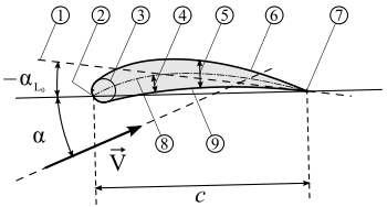 Profile geometry – 1: Zero lift line; 2: Leading edge; 3: Nose circle; 4: Camber; 5: Max. thickness; 6: Upper surface; 7: Trailing edge; 8: Camber mean-line; 9: Lower surface
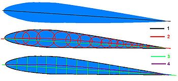 Profile lines – 1: Chord, 2: Camber, 3: Length, 4: Midline
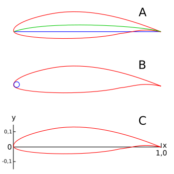 A: blue line = chord, green line = camber mean-line, B: leading edge radius, C: x-y-coordinates for the profile geometry (Chord = x-Axis; y-Axis line on that leading edge)
The NACA airfoils are airfoil shapes for aircraft wings developed by the National Advisory Committee for Aeronautics (NACA). The shape of the NACA airfoils is described using a series of digits following the word "NACA." The parameters in the numerical code can be entered into equations to precisely generate the cross-section of the airfoil and calculate its properties.
Contents
Four-digit series
The NACA four-digit wing sections define the profile by:[1]
- One digit describing maximum camber as percentage of the chord.
- One digit describing the distance of maximum camber from the airfoil leading edge in tens of percent's of the chord.
- Two digits describing maximum thickness of the airfoil as percent of the chord.
For example, the NACA 2412 airfoil has a maximum camber of 2% located 40% (0.4 chords) from the leading edge with a maximum thickness of 12% of the chord. Four-digit series airfoils by default have maximum thickness at 30% of the chord (0.3 chords) from the leading edge.
The NACA 0015 airfoil is symmetrical, the 00 indicating that it has no camber. The 15 indicates that the airfoil has a 15% thickness to chord length ratio: it is 15% as thick as it is long.
Equation for a symmetrical 4-digit NACA airfoil
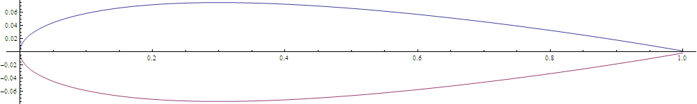
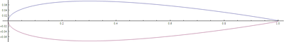 Plot of a NACA 0015 foil, generated from formula
The formula for the shape of a NACA 00xx foil, with "xx" being replaced by the percentage of thickness to chord, is:[2]
where:
- c is the chord length,
- x is the position along the chord from 0 to c,
- y is the half thickness at a given value of x (centerline to surface), and
- t is the maximum thickness as a fraction of the chord (so 100 t gives the last two digits in the NACA 4-digit denomination).
Note that in this equation, at (x/c) = 1 (the trailing edge of the airfoil), the thickness is not quite zero. If a zero-thickness trailing edge is required, for example for computational work, one of the coefficients should be modified such that they sum to zero. Modifying the last coefficient (i.e. to -0.1036) will result in the smallest change to the overall shape of the airfoil. The leading edge approximates a cylinder with a radius of:
Now the coordinates (xU,yU) of the upper airfoil surface, and (xL,yL) of the lower airfoil surface are:
Equation for a cambered 4-digit NACA airfoil
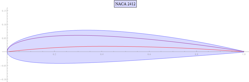
 Plot of a NACA 2412 foil, including camber line and thickness
The simplest asymmetric foils are the NACA 4 digit series foils, which use the same formula as that used to generate the 00xx symmetric foils, but with the line of mean camber bent. The formula used to calculate the mean camber line is:[2]
where:
- m is the maximum camber (100 m is the first of the four digits),
- p is the location of maximum camber (10 p is the second digit in the NACA xxxx description).
For this cambered airfoil, the coordinates (xU,yU) and (xL,yL), of respectively the upper and lower airfoil surface, become:[5]
where
Five-digit series
The NACA five-digit series describes more complex airfoil shapes:[6]
- The first digit, when multiplied by 0.15, gives the designed coefficient of lift (CL).
- Second and third digits, when divided by 2, give p, the distance of maximum camber from the leading edge (as per cent of chord).
- Fourth and fifth digits give the maximum thickness of the airfoil (as per cent of the chord).
For example, the NACA 12018 airfoil would give an airfoil with maximum thickness of 18% chord, maximum camber located at 10% chord, with a lift coefficient of 0.15
The camber-line is defined in two sections:
where the chordwise location x and the ordinate y have been normalized by the chord. The constant m is chosen so that the maximum camber occurs at x = p; for example, for the 230 camber-line, p = 0.3 / 2 = 0.15 and m = 0.2025. Finally, constant k1 is determined to give the desired lift coefficient; for camber-line 230 again, k1 = 15.957 is used.
Modifications
Four- and five-digit series airfoils can be modified with a two-digit code preceded by a hyphen in the following sequence:
- One digit describing the roundness of the leading edge with 0 being sharp, 6 being the same as the original airfoil, and larger values indicating a more rounded leading edge.
- One digit describing the distance of maximum thickness from the leading edge in tens of percent of the chord.
For example, the NACA 1234-05 is a NACA 1234 airfoil with a sharp leading edge and maximum thickness 50% of the chord (0.5 chords) from the leading edge.
In addition, for a more precise description of the airfoil all numbers can be presented as decimals.
1-series
A new approach to airfoil design pioneered in the 1930s in which the airfoil shape was mathematically derived from the desired lift characteristics. Prior to this, airfoil shapes were first created and then had their characteristics measured in a wind tunnel. The 1-series airfoils are described by five digits in the following sequence:
- The number "1" indicating the series
- One digit describing the distance of the minimum pressure area in tens of percent of chord.
- A hyphen.
- One digit describing the lift coefficient in tenths.
- Two digits describing the maximum thickness in percent of chord.
For example, the NACA 16-123 airfoil has minimum pressure 60% of the chord back with a lift coefficient of 0.1 and maximum thickness of 23% of the chord.
6-series
An improvement over 1-series airfoils with emphasis on maximizing laminar flow. The airfoil is described using six digits in the following sequence:
- The number "6" indicating the series.
- One digit describing the distance of the minimum pressure area in tens of percent of chord.
- The subscript digit gives the range of lift coefficient in tenths above and below the design lift coefficient in which favorable pressure gradients exist on both surfaces
- A hyphen.
- One digit describing the design lift coefficient in tenths.
- Two digits describing the maximum thickness in tens of percent of chord.
For example, the NACA 612-315 a=0.5 has the area of minimum pressure 10% of the chord back, maintains low drag 0.2 above and below the lift coefficient of 0.3, has a maximum thickness of 15% of the chord, and maintains laminar flow over 50% of the chord.
7-series
Further advancement in maximizing laminar flow achieved by separately identifying the low pressure zones on upper and lower surfaces of the airfoil. The airfoil is described by seven digits in the following sequence:
- The number "7" indicating the series.
- One digit describing the distance of the minimum pressure area on the upper surface in tens of percent of chord.
- One digit describing the distance of the minimum pressure area on the lower surface in tens of percent of chord.
- One letter referring to a standard profile from the earlier NACA series.
- One digit describing the lift coefficient in tenths.
- Two digits describing the maximum thickness in tens of percent of chord.
- "a=" followed by a decimal number describing the fraction of chord over which laminar flow is maintained. a=1 is the default if no value is given.
For example, the NACA 712A315 has the area of minimum pressure 10% of the chord back on the upper surface and 20% of the chord back on the lower surface, uses the standard "A" profile, has a lift coefficient of 0.3, and has a maximum thickness of 15% of the chord.
8-series
Supercritical airfoils designed to independently maximize airflow above and below the wing. The numbering is identical to the 7-series airfoils except that the sequence begins with an "8" to identify the series.
See also
References
- ^ E. N. Jacobs, K. E. Ward, & R. M. Pinkerton 1933 The characteristics of 78 related airfoil sections from tests in the variable-density wind tunnel, NACA Report No. 460.
- ^ a b Moran, Jack (2003). An introduction to theoretical and computational aerodynamics. Dover. p. 7. ISBN 0486428796. http://books.google.com/?id=4eVP3yWZ1LgC.
- ^ http://www.aerospaceweb.org/question/airfoils/q0041.shtml
- ^ http://www.fges.demon.co.uk/cfd/naca.html#07
- ^ Marzocca, Pier. "The NACA airfoil series" (PDF). Clarkson University. http://people.clarkson.edu/~pmarzocc/AE429/The%20NACA%20airfoil%20series.pdf. Retrieved 07-03-2009.
- ^ E. N. Jacobs & R. M. Pinkerton 1936 Test in the variable-density wind tunnel of related airfoils having the maximum camber unusually far forward, NACA Report No. 537.
External links
- NACA 4 & 5-digit aerofoil generator - Website deactivated - last checked 2010-10-30
- David Lednicer's NACA airfoil coordinate generation program Before running this Windows 95 executable, read this.
- NACA 4 & 5-digit Excel spreadsheets
- List of airfoils used by different aircraft
- Database with images and coordinates of many airfoils
- NACA Airfoil Series
Categories:- Aerodynamics
- Wing design


![y_t = \frac{t}{0.2}c\, \left[ 0.2969 \sqrt{\frac{x}{c}} - 0.1260 \left(\frac{x}{c}\right) - 0.3516 \left(\frac{x}{c}\right)^2 + 0.2843 \left(\frac{x}{c}\right)^3 - 0.1015 \left( \frac{x}{c} \right)^4 \right],](d/0cd31a5e8db6e8435a19e37e41e319d9.png)


Wikimedia Foundation. 2010.