- Siphon
-
Not to be confused with Psiphon.This article is about the domestic device. For the animal organ, see siphon (disambiguation).
 Siphon principle
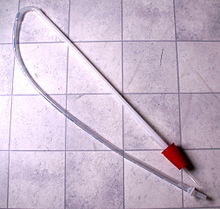 A siphon used for homebrewing beer
The word siphon (Greek: Σίφων, also spelled syphon) is sometimes used to refer to a wide variety of devices that involve the flow of liquids through tubes. But in the English language today, the word siphon usually refers to a tube in an inverted U shape which causes a liquid to flow uphill, above the surface of the reservoir, without pumps, powered by the fall of the liquid as it flows down the tube under the pull of gravity, and is discharged at a level lower than the surface of the reservoir. In practical siphons, atmospheric pressure pushes the liquid up the tube into the region of reduced pressure at the top of the tube. The reduced pressure is caused by liquid falling on the exit side. In the laboratory, some siphons have been demonstrated to work in a vacuum,[1][2][3][4][5] indicating the tensile strength of the liquid is contributing to the operation of siphons at very low pressures.
History
Egyptian reliefs from 1500 BC depict siphons used to extract liquids from large storage jars.[6]
We have physical evidence for the use of siphons by Greek engineers in the 3rd century BC at Pergamon.[7]
Hero of Alexandria wrote extensively about siphons in the treatise Pneumatica.[8]
In the 9th century, the Banu Musa brothers invented a double-concentric siphon, which they described in their Book of Ingenious Devices.[9]
Operation
Theory
A siphon works because gravity pulling down on the taller column of liquid causes reduced pressure at the top of the siphon. This reduced pressure means gravity pulling down on the shorter column of liquid is not sufficient to keep the liquid stationary so it flows from the upper reservoir, up and over the top of the siphon.[10][11]
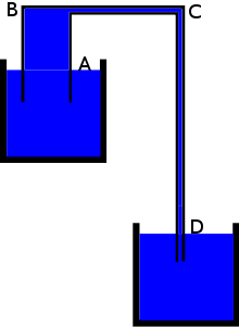 Even the falling lighter lower leg from C to D can cause the liquid of the heavier upper leg to flow up and over into the lower reservoir[12]
An occasional misunderstanding of siphons is that they rely on the tensile strength of the liquid to pull the liquid up and over the rise.[10][11] While water has been found to have a great deal of tensile strength in some experiments (such as with the z-tube[13]), and siphons in vacuum rely on such cohesion, common siphons can easily be demonstrated to need no liquid tensile strength at all to function.[4][10][11] Furthermore, since common siphons operate at positive pressures throughout the siphon, there is no contribution from liquid tensile strength, because the molecules are actually repelling each other in order to resist the pressure, rather than pulling on each other.[4] To demonstrate, the longer lower leg of a common siphon can be plugged at the bottom and filled almost to the crest with liquid, leaving the top and the shorter upper leg completely dry and containing only air. When the plug is removed and the liquid in the longer lower leg is allowed to fall, the liquid in the upper reservoir will then typically sweep the air bubble down and out of the tube. The apparatus will then continue to operate as a siphon. As there is no contact between the liquid on either side of the siphon at the beginning of this experiment, there can be no cohesion between the liquid molecules to pull the liquid over the rise. Another simple demonstration that liquid tensile strength isn't needed in the siphon is to simply introduce a bubble into the siphon during operation. The bubble can be large enough to entirely disconnect the liquids in the tube before and after it, defeating any liquid tensile strength, and yet if the bubble isn't too big, the siphon will continue to operate with little change.
The uphill flow of water in a siphon doesn’t violate the principle of continuity because the mass of water entering the tube and flowing upwards is equal to the mass of water flowing downwards and leaving the tube. A siphon doesn't violate the principle of conservation of energy because the loss of gravitational potential energy as liquid flows from the upper reservoir to the lower reservoir equals the work done in overcoming fluid friction as the liquid flows through the tube.[14] Once started, a siphon requires no additional energy to keep the liquid flowing up and out of the reservoir. The siphon will draw liquid out of the reservoir until the level falls below the intake, allowing air or other surrounding gas to break the siphon, or until the outlet of the siphon equals the level of the reservoir, whichever comes first.
The maximum height of the crest is limited by atmospheric pressure, the density of the liquid, and its vapour pressure. When the pressure within the liquid drops to below the liquid's vapor pressure, tiny vapor bubbles can begin to form at the high point and the siphon effect will end. This effect depends on how efficiently the liquid can nucleate bubbles; in the absence of impurities or rough surfaces to act as easy nucleation sites for bubbles, siphons can temporarily exceed their standard maximum height during the extended time it takes bubbles to nucleate. For water at standard atmospheric pressure, the maximum siphon height is approximately 10 m (32 feet); for mercury it is 76 cm (30 inches).
Analogy
 The chain model is a useful but flawed analogy to the operation of a siphon
A simplified conceptual model of a siphon is that it is like a chain hanging over a pulley with one end of the chain piled on a higher surface than the other. Since the length of chain on the shorter side is lighter than the length of chain on the taller side, the chain will move up around the pulley and down towards the lower surface.[15]
There are two problems with the chain model of a siphon. The first is that under most practical circumstances, dissolved gases, vapor pressure, and (sometimes) lack of adhesion with tube walls, conspire to render the tensile strength within the liquid ineffective for siphoning. Thus, unlike a chain which has significant tensile strength, liquids usually have little tensile strength under typical siphon conditions, and therefore the liquid on the rising side cannot be pulled up, in the way the chain is pulled up on the rising side.[11][4]
The second problem with the chain model of the siphon is that the weight of liquid on the up side of the siphon can be greater than the liquid on the down side, yet the siphon can still function. For example, if the tube from the upper reservoir to the top of the siphon has a much larger diameter than the section of tube from the lower reservoir to the top of the siphon, the shorter upper section of the siphon may have a much larger weight of liquid in it, yet the siphon can function normally.[12]
Practical requirements
A plain tube can be used as a siphon. An external pump has to be applied to start the liquid flowing and prime the siphon. This can be a human mouth. This is sometimes done with any leak-free hose to siphon gasoline from a motor vehicle's gasoline tank to an external tank. (Siphoning gasoline by mouth often results in the accidental swallowing of gasoline, which is quite poisonous, or aspirating it into the lungs, which can cause death or lung damage.[16]) If the tube is flooded with liquid before part of the tube is raised over the intermediate high point and care is taken to keep the tube flooded while it is being raised, no pump is required. Devices sold as siphons come with a siphon pump to start the siphon process. When applying a siphon to any application it is important that the piping be as closely sized to the requirement as possible. Using piping of too great a diameter and then throttling the flow using valves or constrictive piping appears to increase the effect of previously cited concerns over gases or vapor collecting in the crest which serve to break the vacuum. Once the vacuum is reduced the siphon effect is lost.
Reducing the size of pipe used closer to requirements appears to reduce this effect and creates a more functional siphon that does not require constant re-priming and restarting. In this respect, where the requirement is to match a flow into a container with a flow out of said container (to maintain a constant level in a pond fed by a stream, for example) it would be preferable to utilize two or three smaller separate parallel pipes that can be started as required rather than attempting to use a single large pipe and attempting to throttle it.
Applications
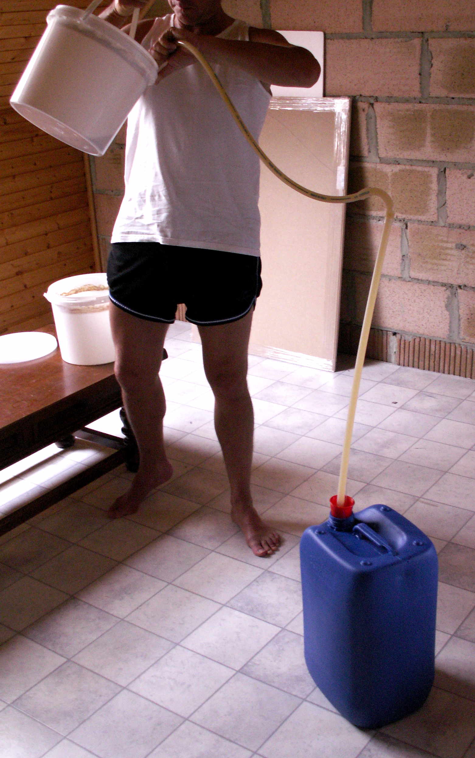
 Siphoning the beer after a first fermentation
When certain liquids needs to be purified, siphoning can help prevent either the bottom (dregs) or the top (foam and floaties) from being transferred out of one container into a new container. Siphoning is thus useful in the fermentation of wine and beer for this reason, since it can keep unwanted impurities out of the new container.
Self-constructed siphons, made of pipes or tubes, can be used to evacuate water from cellars after floodings. Between the flooded cellar and a deeper place outside a connection is built, using a tube or some pipes. They are filled with water through an intake valve (at the highest end of the construction). When the ends are opened, the water flows through the pipe into the sewer or the river.
Siphoning is common in irrigated fields to transfer a controlled amount of water from a ditch, over the ditch wall, into furrows.
Large siphons may be used in municipal waterworks and industry. Their size requires control via valves at the intake, outlet and crest of the siphon. The siphon may be primed by closing the intake and outlets and filling the siphon at the crest. If intakes and outlets are submerged, a vacuum pump may be applied at the crest to prime the siphon. Alternatively the siphon may be primed by a pump at either the intake or outlet.
Gas in the liquid is a concern in large siphons.[17] The gas tends to accumulate at the crest and if enough accumulates to break the flow of liquid, the siphon stops working. The siphon itself will exacerbate the problem because as the liquid is raised through the siphon, the pressure drops, causing dissolved gases within the liquid to come out of solution. Higher temperature accelerates the release of gas from liquids so maintaining a constant, low temperature helps. The longer the liquid is in the siphon, the more gas is released, so a shorter siphon overall helps. Local high points will trap gas so the intake and outlet legs should have continuous slopes without intermediate high points. The flow of the liquid moves bubbles thus the intake leg can have a shallow slope as the flow will push the gas bubbles to the crest. Conversely, the outlet leg needs to have a steep slope to allow the bubbles to move against the liquid flow; though other designs call for a shallow slope in the outlet leg as well to allow the bubbles to be carried out of the siphon. At the crest the gas can be trapped in a chamber above the crest. The chamber needs to be occasionally primed again with liquid to remove the gas.
Siphon terminology
Bowl siphon
Bowl siphons are part of flush toilets. Siphon action in the bowl siphon siphons out the contents of the toilet bowl and creates the characteristic toilet "sucking" sound.
Some toilets also use the siphon principle to obtain the actual flush from the cistern. The flush is triggered by a lever or handle that operates a simple diaphragm-like piston pump that lifts enough water to the crest of the siphon to start the flow of water which then completely empties the contents of the cistern into the toilet bowl. The advantage of this system was that no water would leak from the cistern excepting when flushed.
Early urinals incorporated a siphon in the cistern which would flush automatically on a regular cycle because there was a constant trickle of clean water being fed to the cistern by a slightly open valve.
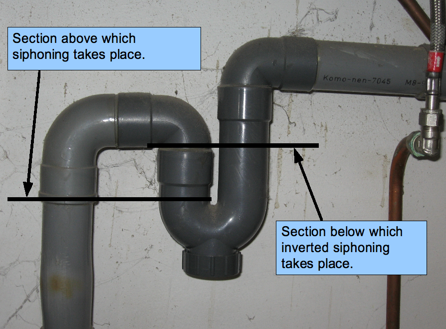
 Trap under a sink which functions as a siphon
Inverted siphon
See also: Trap (plumbing)An inverted siphon is not a siphon but a term applied to pipes that must dip below an obstruction to form a "U" shaped flow path. Inverted siphons are commonly called traps for their function in preventing smelly sewer gases from coming back out of drains and sometimes making dense objects like rings and electronic components retrievable after falling into a drain.[citation needed] Liquid flowing in one end simply forces liquid up and out the other end, but solids like sand will accumulate. This is especially important in sewage systems or culverts which must be routed under rivers or other deep obstructions where the better term is "depressed sewer". Large inverted siphons are used to convey water being carried in canals or flumes across valleys, for irrigation or gold mining.
Back siphonage
Back siphonage is a plumbing term applied to clean water pipes that connect directly into a reservoir without an air gap. As water is delivered to other areas of the plumbing system at a lower level, the siphon effect will tend to siphon water back out of the reservoir. This may result in contamination of the water in the pipes. Back siphonage is not to be confused with backflow. Back siphonage is a result of liquids at a lower level drawing water from a higher level. Backflow is driven entirely by pressure in the reservoir itself. Backflow cannot occur through an intermediate high-point. Back siphonage can flow through an intermediate high-point and is thus much more difficult to guard against.
Anti-siphon valve
Anti-siphon valves[18] are required in such designs. Building codes often contain specific sections on back siphonage and especially for external faucets. (See sample building code below.) The reason is that external faucets may be attached to hoses which may be immersed in an external body of water, such as a garden pond, swimming pool, aquarium or washing machine. Should the pressure within the water supply system fall, the external water may be siphoned back into the drinking water system through the faucet. Another possible contamination point is the water intake in the toilet tank. An anti-siphon valve is also required here to prevent pressure drops in the water supply line from siphoning water out of the toilet tank (which may contain additives such as "toilet blue") and contaminating the water system. Anti-siphon valves function as a one-direction check valve.
Anti-siphon valves are also used medically. Hydrocephalus, or excess fluid in the brain, may be treated with a shunt which drains cerebrospinal fluid from the brain. All shunts have a valve to relieve excess pressure in the brain. The shunt may lead into the abdominal cavity such that the shunt outlet is significantly lower than the shunt intake when the patient is standing. Thus a siphon effect may take place and instead of simply relieving excess pressure, the shunt may act as a siphon, completely draining cerebrospinal fluid from the brain. The valve in the shunt may be designed to prevent this siphon action so that negative pressure on the drain of the shunt does not result in excess drainage. Only excess positive pressure from within the brain should result in drainage.[19][20][21]
Note that the anti-siphon valve in medical shunts is preventing excess forward flow of liquid. In plumbing systems, the anti-siphon valve is preventing backflow.
Other anti-siphoning devices
Along with anti-siphon valves, anti-siphoning devices also exist. The two are unrelated in application. Siphoning can be used to remove fuel from tanks. With the cost of fuel increasing, it has been linked in several countries globally to the rise in fuel theft. Trucks, with their large fuel tanks, are most vulnerable. The anti-siphon device prevents thieves from inserting a tube into the fuel tank.
Siphon barometer
A siphon barometer is the term sometimes applied to the simplest of mercury barometers. A continuous U-shaped tube of the same diameter throughout is sealed on one end and filled with mercury. When placed into the upright position, mercury will flow away from the sealed end, forming a partial vacuum, until balanced by atmospheric pressure on the other end. The term "siphon" is used because the same principle of atmospheric pressure acting on a fluid is applied. The difference in height of the fluid between the two arms of the U-shaped tube is the same as the maximum intermediate height of a siphon. When used to measure pressures other than atmospheric pressure, a siphon barometer is sometimes called a siphon gauge and not to be confused with a siphon rain gauge. Siphon pressure gauges are rarely used today.
Siphon bottle
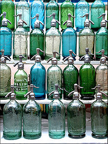 Siphon bottles
A siphon bottle (also called a soda syphon or, archaically, a siphoid[22]) is a pressurized bottle with a vent and a valve. Pressure within the bottle drives the liquid up and out a tube. It is a siphon in the sense that pressure drives the liquid through a tube. A special form was the gasogene.
Siphon cup
A siphon cup is the (hanging) reservoir of paint attached to a spray gun. This is to distinguish it from gravity-fed reservoirs. An archaic use of the term is a cup of oil in which the oil is siphoned out of the cup via a cotton wick or tube to a surface to be lubricated.
Siphon rain gauge
A siphon rain gauge is a rain gauge that can record rainfall over an extended period. A siphon is used to automatically empty the gauge. It is often simply called a "siphon gauge" and is not to be confused with a siphon pressure gauge.
Heron's siphon
Heron's siphon is a siphon that works on positive air pressure and at first glance appears to be a perpetual motion machine. In a slightly differently configuration, it is also known as Heron's fountain.[23]
Venturi Siphon
A venturi siphon, also known as an eductor, is essentially a venturi which is designed to greatly speed up the fluid flowing in a pipe such that an inlet port located at the throat of the venturi can be used to siphon another fluid. See pressure head. The low pressure at the throat of the venturi is called a siphon when a second fluid is introduced, or an aspirator when the fluid is air.
Siphonic roof drainage
Siphonic roof drainage makes use of the siphoning principle to carry water horizontally from multiple roof drains to a single downpipe and to increase flow velocity.[24] Air baffles at the roof drain inlets reduce the injection of air which causes embolisms in siphons. One benefit to this drainage technique is the reduction in required pipe diameter to drain a given roof surface area, up to half the size. Another benefit is the elimination of pipe pitch or gradient required for conventional roof drainage piping.
Siphon spillway
A siphon spillway in a dam uses the siphon effect to increase the flow rate. A normal spillway flow is pressurized by the height of the reservoir above the spillway whereas a siphon flow rate is governed by the difference in height of the inlet and outlet. (See math section below.)
Sample building code regulations regarding back siphonage
From Ontario's building code:[25]
- 7.6.2.3.Back Siphonage
- Every potable water system that supplies a fixture or tank that is not subject to pressures above atmospheric shall be protected against back-siphonage by a backflow preventer.
- Where a potable water supply is connected to a boiler, tank, cooling jacket, lawn sprinkler system or other device where a non-potable fluid may be under pressure that is above atmospheric or the water outlet may be submerged in the non-potable fluid, the water supply shall be protected against backflow by a backflow preventer.
- Where a hose bibb is installed outside a building, inside a garage, or where there is an identifiable risk of contamination, the potable water system shall be protected against backflow by a backflow preventer.
Self-siphons
The term self-siphon is used in a number of ways. Liquids that are composed of long polymers can "self-siphon"[26][27] and these liquids do not depend on atmospheric pressure. Self-siphoning polymer liquids work the same as the siphon-chain model where the lower part of the chain pulls the rest of the chain up and over the crest. This phenomenon is also called a tubeless siphon.[28]
"Self-siphon" is also often used in sales literature by siphon manufacturers to describe portable siphons that contain a pump. With the pump, no external suction (e.g. from a person's mouth/lungs) is required to start the siphon and thus the product is described as a "self-siphon".
If the upper reservoir is such that the liquid there can rise above the height of the siphon crest, the rising liquid in the reservoir can "self-prime" the siphon and the whole apparatus be described as a "self-siphon".[29] Once primed, such a siphon will continue to operate until the level of the upper reservoir falls below the intake of the siphon. Such self-priming siphons are useful in some rain gauges and dams.
Capillary action can be used in self-priming siphons. In these, water soaks upwards (into a cotton-filled hose) and below the crest to begin the siphon gradually, and as weight is added to the down stream, this kind of siphon will speed up, but it will never be as fast as the same diameter of open hose.
Siphons in nature
Anatomy
The term "siphon" is used for a number of structures in human and animal anatomy, either because flowing liquids are involved or because the structure is shaped like a siphon, but in which no actual siphon effect is occurring: see Siphon (biology).
Biologists debate whether the siphon mechanism plays a role in blood circulation.[30] It is theorized that veins form a continuous loop with arteries such that blood flowing down veins help siphon blood up the arteries, especially in giraffes and snakes.[31] Some have concluded that the siphon mechanism aids blood circulation in giraffes.[32] Many others dispute this[33][34] and experiments show no siphon effects in human circulation.[35] Some cite negative pressure in the brain as supporting the role of the siphon effect in the brain.[36]
Geology
In speleology, a siphon is that part of a cave passage that lies under water and through which cavers have to dive to progress along it.
Explanation using Bernoulli's equation
Bernoulli's equation may be applied to a siphon to derive the flow rate and maximum height of the siphon.
 Example of a siphon with annotations to describe Bernoulli's equation
- Let the surface of the upper reservoir be the reference elevation.
- Let point A be the start point of siphon, immersed within the higher reservoir and at a depth −d below the surface of the upper reservoir.
- Let point B be the intermediate high point on the siphon tube at height +hB above the surface of the upper reservoir.
- Let point C be the drain point of the siphon at height −hC below the surface of the upper reservoir.
Bernoulli's equation:

 = fluid velocity along the streamline
 = gravitational acceleration downwards
 = elevation in gravity field
 = pressure along the streamline
 = fluid density
Apply Bernoulli's equation to the surface of the upper reservoir. The surface is technically falling as the upper reservoir is being drained. However, for this example we will assume the reservoir to be infinite and the velocity of the surface may be set to zero. Furthermore, the pressure at both the surface and the exit point C is atmospheric pressure. Thus:
 (Equation 1.)
Apply Bernoulli's equation to point A at the start of the siphon tube in the upper reservoir where P = PA, v = vA and y = −d
 (Equation 2.)
Apply Bernoulli's equation to point B at the intermediate high point of the siphon tube where P = PB, v = vB and y = hB
 (Equation 3.)
Apply Bernoulli's equation to point C where the siphon empties. Where v = vC and y = −hC. Furthermore, the pressure at the exit point is atmospheric pressure. Thus:
 (Equation 4.)
Velocity
As the siphon is a single system, the constant in all four equations is the same. Setting equations 1 and 4 equal to each other gives:
Solving for vC:
- Velocity of siphon:
The velocity of the siphon is thus driven solely by the height difference between the surface of the upper reservoir and the drain point. The height of the intermediate high point, hB, does not affect the velocity of the siphon. However, as the siphon is a single system, vB = vC and the intermediate high point does limit the maximum velocity. The drain point cannot be lowered indefinitely to increase the velocity. Equation 3 will limit the velocity to a positive pressure at the intermediate high point to prevent cavitation. The maximum velocity may be calculated by combining equations 1 and 3:
Setting PB = 0 and solving for vmax:
- Maximum velocity of siphon:

The depth, −d, of the initial entry point of the siphon in the upper reservoir, does not affect the velocity of the siphon. No limit to the depth of the siphon start point is implied by Equation 2 as pressure PA increases with depth d. Both these facts imply the operator of the siphon may bottom skim or top skim the upper reservoir without impacting the siphon's performance.
Note that this equation for the velocity is the same as that of any object falling height hC. Note also that this equation assumes PC is atmospheric pressure. If the end of the siphon is below the surface, the height to the end of the siphon cannot be used; rather the height difference between the reservoirs should be used.
Maximum height
Setting equations 1 and 3 equal to each other gives:
Maximum height of the intermediate high point occurs when it is so high that the pressure at the intermediate high point is zero; in typical scenarios this will cause the liquid to form bubbles and if the bubbles enlarge to fill the pipe then the siphon will 'break'. Setting PB = 0:
Solving for hB:
- General height of siphon:
This means that the height of the intermediate high point is limited by velocity of the siphon. Faster siphons result in lower heights. Height is maximized when the siphon is very slow and vB = 0:
- Maximum height of siphon:

This is the maximum height that a siphon will work. It is simply when the weight of the column of liquid to the intermediate high point equates to atmospheric pressure. Substituting values will give approximately 10 metres for water and 0.76 metres for mercury.
Vacuum siphons
Experiments have shown that siphons can operate in a vacuum, provided that the liquids are pure and degassed and surfaces are very clean.[1][2][3][4][5][37][38]
Oxford English Dictionary
The Oxford English Dictionary (OED) entry on siphon, published in 1911, states that a siphon works by atmospheric pressure. Stephen Hughes of Queensland University of Technology criticised this in a 2010 article[15] which was widely reported in the media.[39][40][41][42] The OED editors stated, "there is continuing debate among scientists as to which view is correct. ... We would expect to reflect this debate in the fully updated entry for siphon, due to be published later this year."[43] Dr. Hughes continued to defend his view of the siphon in a late September post at the Oxford blog.[44] A set of experiments was recently published, seriously questioning Hughes's hypothesis. [10]
See also
- Communicating vessels
- 1992 explosion in Guadalajara for details of an accident involving a siphon.
- Gravity feed
References
- ^ a b "Video Demonstration of Siphon in Vacuum". http://www.youtube.com/watch?v=8F4i9M3y0ew.
- ^ a b Minor, Ralph Smith (1914). "Would a Siphon Flow in a Vacuum! Experimental Answers". School Science and Mathematics. 14,2: 152. http://commons.wikimedia.org/wiki/File:Would_a_siphon_flow_in_a_vacuum_experimental_answers.pdf.
- ^ a b Duane1902
- ^ a b c d e http://www.mindspring.com/~rwramette/nokes.pdf Nokes M C 1948 "Vacuum siphons" School Science Review 29 233
- ^ a b Siphon Concepts
- ^ Usher, Abbott Payson (April 1, 1988). A History of Mechanical Inventions (Revised Edition). Dover Publications. p. 461. ISBN 978-0486255934. http://print.google.com/print?id=xuDDqqa8FlwC&pg=93&lpg=93&dq=siphon+vacuum&sig=Rv57Nd2RzUgKoz58zrP1BKqpH_I&auth=DQAAAGsAAABhdj2gK7YELIVEZdsG3IH-FT4vEQAnsHKdFbCsD0h61ukaejc3D-jxmBy7UlR0ykMcybLZ01jMj88yM4izr039yiMQbqqw6jIHxekeEm13thfbOsRjpR_s2Xt3lGTIDe0A472OREwbsvVy91tPSjAo.
- ^ Dora P. Crouch (1993). "Water management in ancient Greek cities". Oxford University Press US. p. 119. ISBN 0-19-507280-4
- ^ "THE PNEUMATICS OF HERO OF ALEXANDRIA". www.history.rochester.edu. http://www.history.rochester.edu/steam/hero/index.html. Retrieved 2010-05-11.
- ^ Banu Musa (authors), Donald Routledge Hill (translator) (1979). The book of ingenious devices (Kitāb al-ḥiyal). Springer. p. 21. ISBN 9027708339.
- ^ a b c d e http://hawaii.edu/news/article.php?aId=4128
- ^ a b c d e "The Great Siphon Definition Debate". http://www.youtube.com/watch?v=T_FJe-HdFPw. Retrieved 2010-05-31.[unreliable source?]
- ^ a b "The Pulley Analogy Does Not Work For Every Siphon". http://www.fmf.uni-lj.si/~planinsic/PEM/pulley%20siphon.wmv.
- ^ Smith, Andrew M. (1991). "Negative Pressure Generated by Octopus Suckers: A Study of the Tensile Strength of Water in Nature". Journal of Experimental Biology 157 (1): 257–271. http://jeb.biologists.org/cgi/content/abstract/157/1/257.
- ^ Streeter, Victor L., Fluid Mechanics, Section 10.2 (4th edition), McGraw-Hill, New York, USA. Library of Congress Catalog Card No. 66-15605
- ^ a b Hughes, Stephen W (2010). "A practical example of a siphon at work". Physics Education 45 (2): 162–166. Bibcode 2010PhyEd..45..162H. doi:10.1088/0031-9120/45/2/006. http://eprints.qut.edu.au/31098/8/31098a.pdf.
- ^ "Material Safety Data Sheet for MidGrade Unleaded Gasoline". 2006-11-28. http://www.marathonpetroleum.com/content/documents/mpc/msds/0125MAR019.pdf.
- ^ "Siphons for Geosiphon Treatment Systems". sti.srs.gov. http://sti.srs.gov/fulltext/tr2000066/tr2000066.html. Retrieved 2010-05-11.
- ^ "Toiletology ... Anti-siphon needs an explanation". www.toiletology.com. http://www.toiletology.com/anti-sph.shtml. Retrieved 2010-05-11.
- ^ Tokoro, Kazuhiko; Chiba, Yasuhiro; Abe, Hiroyuki; Tanaka, Nobumasa; Yamataki, Akira; Kanno, Hiroshi (1994). "Importance of anti-siphon devices in the treatment of pediatric hydrocephalus". Child's Nervous System 10 (4): 236–8. doi:10.1007/BF00301160.
- ^ "Hydrocephalus and Shunts in the Person with Spina Bifida" (Press release). Spina Bifida Association of America. 2009. http://www.spinabifidaassociation.org/site/c.liKWL7PLLrF/b.2725875/k.BDDF/Hydrocephalus_and_Shunts_in_the_Person_with_Spina_Bifida.htm. Retrieved November 9, 2010.
- ^ Zemack, Göran; Romner, Bertil (1999). "Seven-year clinical experience with the Codman Hakim programmable valve: a retrospective study of 583 patients". Neurosurgical FOCUS 7 (4): 941–8. doi:10.3171/foc.1999.7.4.11.
- ^ http://voronoi.ics.uci.edu/cgi-bin/Dict?Form=Dict2&Database=*&Query=siphoid[dead link]
- ^ Kezerashvili; Sapozhnikov (2003). "Magic Fountain". arXiv:physics/0310039v1 [physics.ed-ph].
- ^ Arthur, S; Wright, G (2007). "Siphonic roof drainage systems—priming focused design". Building and Environment 42 (6): 2421–31. doi:10.1016/j.buildenv.2006.08.021.
- ^ [1][dead link]
- ^ "Physics Demonstrations - Light". sprott.physics.wisc.edu. http://sprott.physics.wisc.edu/demobook/chapter6.htm. Retrieved 2010-05-11.
- ^ School of Chemistry. Chem.soton.ac.uk. Retrieved on 2010-11-11.
- ^ Tubeless Siphon and Die Swell Demonstration, Christopher W. MacMinn & Gareth H. McKinley, September 26, 2004
- ^ Siphon. Grow.arizona.edu. Retrieved on 2010-11-11.
- ^ [2][dead link]
- ^ Seymour, RS; Arndt, JO (2004). "Independent effects of heart-head distance and caudal blood pooling on blood pressure regulation in aquatic and terrestrial snakes". The Journal of experimental biology 207 (Pt 8): 1305–11. doi:10.1242/jeb.00882. PMID 15010481.
- ^ Hicks, JW; Badeer, HS (1989). "Siphon mechanism in collapsible tubes: application to circulation of the giraffe head". The American journal of physiology 256 (2 Pt 2): R567–71. PMID 2916707.
- ^ Seymour, RS; Johansen, K (1987). "Blood flow uphill and downhill: does a siphon facilitate circulation above the heart?". Comparative biochemistry and physiology. A, Comparative physiology 88 (2): 167–70. doi:10.1016/0300-9629(87)90465-8. PMID 2890463.
- ^ Seymour, RS; Hargens, AR; Pedley, TJ (1993). "The heart works against gravity". The American journal of physiology 265 (4 Pt 2): R715–20. PMID 8238437.
- ^ Dawson, E. A. (2004). "Standing up to the challenge of standing: a siphon does not support cerebral blood flow in humans". AJP: Regulatory, Integrative and Comparative Physiology 287 (4): R911–4. doi:10.1152/ajpregu.00196.2004.
- ^ Hicks, J. W. (2005). "The siphon controversy counterpoint: the brain need not be "baffling"". AJP: Regulatory, Integrative and Comparative Physiology 289 (2): R629–32. doi:10.1152/ajpregu.00810.2004.
- ^ Ganci, S; Yegorenkov, V (2008). "Historical and pedagogical aspects of a humble instrument". European Journal of Physics 29 (3): 421–430. Bibcode 2008EJPh...29..421G. doi:10.1088/0143-0807/29/3/003.
- ^ Nokes M. C. (1948). "Vacuum siphons". Am. J. Phys. 16: 254.
- ^ QUT physicist corrects Oxford English Dictionary
- ^ AOL News, For 99 Years, Oxford English Dictionary Got It Wrong
- ^ Calligeros, Marissa, Dictionary mistake goes unnoticed for 99 years, Brisbane Times, May 10, 2010
- ^ Malkin, Bonnie, Physicist spots 99-year-old mistake in Oxford English Dictionary, The Daily Telegraph (London), 11 May 2010
- ^ "On The Definition of “Siphon”". OUPblog. Oxford University Press. 21 May 2010. http://blog.oup.com/2010/05/siphon/. Retrieved 23 May 2010.
- ^ http://blog.oup.com/2010/05/siphon/comment-page-1/#comment-177572
External links
- The Straight Dope: How Does A Siphon work?
- Pnematics of Hero of Alexandria - Interesting Applications of Siphons
Categories:- Fluid dynamics
- Tools
- 7.6.2.3.Back Siphonage


Wikimedia Foundation. 2010.