- Coupling
-
This article is about a mechanical connection between two objects. For other uses, see Coupling (disambiguation).
 Rotating coupling
A coupling is a device used to connect two shafts together at their ends for the purpose of transmitting power. Couplings do not normally allow disconnection of shafts during operation, however there are torque limiting couplings which can slip or disconnect when some torque limit is exceeded.
The primary purpose of couplings is to join two pieces of rotating equipment while permitting some degree of misalignment or end movement or both. By careful selection, installation and maintenance of couplings, substantial savings can be made in reduced maintenance costs and downtime.
Contents
Uses
Shaft couplings are used in machinery for several purposes, the most common of which are the following.[1]
- To provide for the connection of shafts of units that are manufactured separately such as a motor and generator and to provide for disconnection for repairs or alternations.
- To provide for misalignment of the shafts or to introduce mechanical flexibility.
- To reduce the transmission of shock loads from one shaft to another.
- To introduce protection against overloads.
- To alter the vibration characteristics of rotating units.
Types
Rigid
A rigid coupling is a unit of hardware used to join two shafts within a motor or mechanical system. It may be used to connect two separate systems, such as a motor and a generator, or to repair a connection within a single system. A rigid coupling may also be added between shafts to reduce shock and wear at the point where the shafts meet.
When joining shafts within a machine, mechanics can choose between flexible and rigid couplings. While flexible units offer some movement and give between the shafts, rigid couplings are the most effective choice for precise alignment and secure hold. By precisely aligning the two shafts and holding them firmly in place, rigid couplings help to maximize performance and increase the expected life of the machine. These rigid couplings are available in two basic designs to fit the needs of different applications. Sleeve-style couplings are the most affordable and easiest to use. They consist of a single tube of material with an inner diameter that's equal in size to the shafts. The sleeve slips over the shafts so they meet in the middle of the coupling. A series of set screws can be tightened so they touch the top of each shaft and hold them in place without passing all the way through the coupling.
Clamped or compression rigid couplings come in two parts and fit together around the shafts to form a sleeve. They offer more flexibility than sleeved models, and can be used on shafts that are fixed in place. They generally are large enough so that screws can pass all the way through the coupling and into the second half to ensure a secure hold.Flanged rigid couplings are designed for heavy loads or industrial equipment. They consist of short sleeves surrounded by a perpendicular flange. One coupling is placed on each shaft so the two flanges line up face to face. A series of screws or bolts can then be installed in the flanges to hold them together. Because of their size and durability, flanged units can be used to bring shafts into alignment before they are joined together. Rigid couplings are used when precise shaft alignment is required; shaft misalignment will affect the coupling's performance as well as its life. Examples:
Flexible
Flexible couplings are used to transmit torque from one shaft to another when the two shafts are slightly misaligned. Flexible couplings can accommodate varying degrees of misalignment up to 3°. In addition to allowing for misalignment, flexible couplings can also be used for vibration damping or noise reduction. Flexible couplings are designed to transmit torque while permitting some radial, axial, and angular misalignment. Flexible couplings can accommodate angular misalignment up to a few degrees and some parallel misalignment.
Beam
 A beam coupling
A beam coupling, also known as helical coupling, is a flexible coupling for transmitting torque between two shafts while allowing for angular misalignment, parallel offset and even axial motion, of one shaft relative to the other. This design utilizes a single piece of material and becomes flexible by removal of material along a spiral path resulting in a curved flexible beam of helical shape. Since it is made from a single piece of material, the Beam Style coupling does not exhibit the backlash found in some multi-piece couplings. Another advantage of being an all machined coupling is the possibility to incorporate features into the final product while still keep the single piece integrity.
Changes to the lead of the helical beam provide changes to misalignment capabilities as well as other performance characteristics such as torque capacity and torsional stiffness. It is even possible to have multiple starts within the same helix.
The material used to manufacture the beam coupling also affects its performance and suitability for specific applications such as food, medical and aerospace. Materials are typically aluminum alloy and stainless steel, but they can also be made in acetal, maraging steel and titanium. The most common applications are attaching encoders to shafts and motion control for robotics.
-

A beam coupling with optional features machined into it
-

Increasing number of coils allows for greater angular misalignment
Constant velocity
Main article: Constant-velocity jointThere are various types of constant-velocity (CV) couplings: Rzeppa joint, Double cardan joint, and Thompson coupling.
Diaphragm
Diaphragm couplings transmit torque from the outside diameter of a flexible plate to the inside diameter, across the spool or spacer piece, and then from inside to outside diameter. The deforming of a plate or series of plates from I.D. to O.D accomplishes the misalignment.
Disc
Main article: Disc couplingDisc couplings transmit torque from a driving to a driven bolt tangentially on a common bolt circle. Torque is transmitted between the bolts through a series of thin, stainless steel discs assembled in a pack. Misalignment is accomplished by deforming of the material between the bolts.
Fluid
Main article: Fluid couplingGear
 A gear coupling
A gear coupling is a mechanical device for transmitting torque between two shafts that are not collinear. It consists of a flexible joint fixed to each shaft. The two joints are connected by a third shaft, called the spindle.
Each joint consists of a 1:1 gear ratio internal/external gear pair. The tooth flanks and outer diameter of the external gear are crowned to allow for angular displacement between the two gears. Mechanically, the gears are equivalent to rotating splines with modified profiles. They are called gears because of the relatively large size of the teeth.
Gear couplings and universal joints are used in similar applications. Gear couplings have higher torque densities than universal joints designed to fit a given space while universal joints induce lower vibrations. The limit on torque density in universal joints is due to the limited cross sections of the cross and yoke. The gear teeth in a gear coupling have high backlash to allow for angular misalignment. The excess backlash can contribute to vibration.
Gear couplings are generally limited to angular misalignments, i.e., the angle of the spindle relative to the axes of the connected shafts, of 4-5°. Universal joints are capable of higher misalignments.
Single joint gear couplings are also used to connected two nominally coaxial shafts. In this application the device is called a gear-type flexible, or flexible coupling. The single joint allows for minor misalignments such as installation errors and changes in shaft alignment due to operating conditions. These types of gear couplings are generally limited to angular misalignments of 1/4-1/2°.
Hirth
Main article: Hirth jointOldham
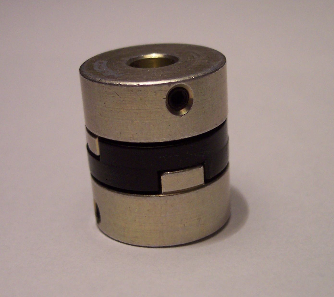
 Animated Oldham coupler
An Oldham coupling has three discs, one coupled to the input, one coupled to the output, and a middle disc that is joined to the first two by tongue and groove. The tongue and groove on one side is perpendicular to the tongue and groove on the other. The middle disc rotates around its center at the same speed as the input and output shafts. Its center traces a circular orbit, twice per rotation, around the midpoint between input and output shafts. Often springs are used to reduce backlash of the mechanism. An advantage to this type of coupling, as compared to two universal joints, is its compact size. The coupler is named for John Oldham who invented it in Ireland, in 1820, to solve a paddle placement problem in a paddle steamer design.
-

Oldham coupler, assembled
-

Oldham coupler, disassembled
Rag joint
Main article: Rag jointRag joints are commonly used on automotive steering linkages and drive trains. When used on a drive train they are sometimes known as giubos.
Universal joint
Main article: Universal jointUniversal joints are also known as Cardan joints.
Others
- Bellows coupling — low backlash
- Elastomeric coupling
- Bushed pin coupling
- Donut coupling
- Spider or jaw coupling (or lovejoy coupling)
- Resilient coupling
- Roller chain and sprocket coupling
Requirements of good shaft alignment / good coupling setup
- it should be easy to connect or disconnect the coupling.
- it does allow some misalignment between the two adjacent shaft rotation axes.
- it is the goal to minimise the remaining misalignment in running operation to maximise power transmission and to maximise machine runtime (coupling and bearing and sealings lifetime).
- it should have no projecting parts.
- it is recommended to use manufacturer's alignment target values to set up the machine train to a defined non-zero alignment, due to the fact that later when the machine is at operation temperature the alignment condition is perfect
Coupling maintenance and failure
Coupling maintenance is generally a simple matter, requiring a regularly scheduled inspection of each coupling. It consists of:
- Performing visual inspections, checking for signs of wear or fatigue, and cleaning couplings regularly.
- Checking and changing lubricant regularly if the coupling is lubricated. This maintenance is required annually for most couplings and more frequently for couplings in adverse environments or in demanding operating conditions.
- Documenting the maintenance performed on each coupling, along with the date.[2]
Even with proper maintenance, however, couplings can fail. Underlying reasons for failure, other than maintenance, include:
- Improper installation
- Poor coupling selection
- Operation beyond design capabilities.[2]
The only way to improve coupling life is to understand what caused the failure and to correct it prior to installing a new coupling. Some external signs that indicate potential coupling failure include:
- Abnormal noise, such as screeching, squealing or chattering
- Excessive vibration or wobble
- Failed seals indicated by lubricant leakage or contamination.[2]
Checking the coupling balance
Couplings are normally balanced at the factory prior to being shipped, but they occasionally go out of balance in operation. Balancing can be difficult and expensive, and is normally done only when operating tolerances are such that the effort and the expense are justified. The amount of coupling unbalance that can be tolerated by any system is dictated by the characteristics of the specific connected machines and can be determined by detailed analysis or experience.[2]
See also
References
External links
Categories:- Mechanisms
- Hardware (mechanical)
- Mechanical engineering


Wikimedia Foundation. 2010.