- Bending (metalworking)
-
"Metal bending" redirects here. For the form of stage magic, see Spoon bending.
 Bending
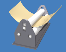
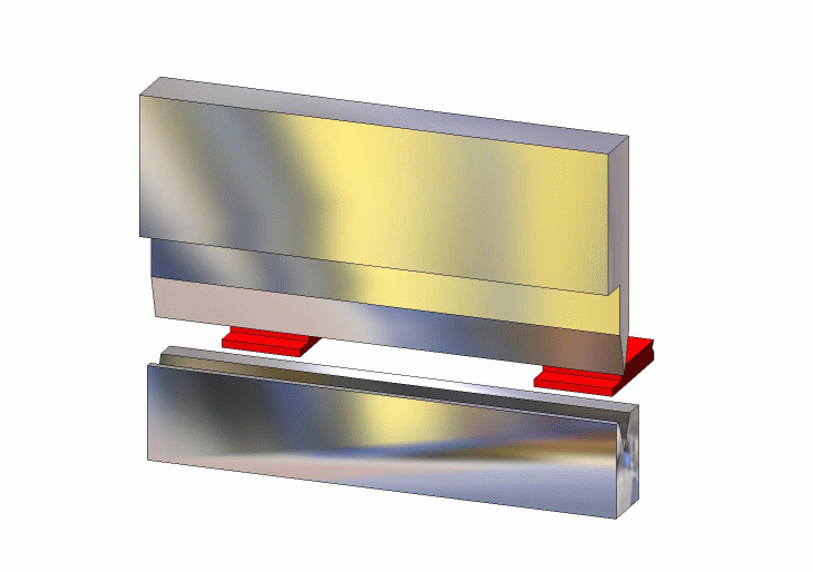
 Press brake
Bending is a manufacturing process that produces a V-shape, U-shape, or channel shape along a straight axis in ductile materials, most commonly sheet metal.[1] Commonly used equipment include box and pan brakes, brake presses, and other specialized machine presses. Typical products that are made like this are boxes such as electrical enclosures and rectangular ductwork.
Contents
Process
 Bending process
In press brake forming, a work piece is positioned over the die block and the die block presses the sheet to form a shape.[1] Usually bending has to overcome both tensile stresses as well as compressive stresses. When bending is done, the residual stresses cause the material to spring back towards its original position, so the sheet must be over-bent to achieve the proper bend angle. The amount of spring back is dependent on the material, and the type of forming. When sheet metal is bent, it stretches in length. The bend deduction is the amount the sheet metal will stretch when bent as measured from the outside edges of the bend. The bend radius refers to the inside radius. The formed bend radius is dependent upon the dies used, the material properties, and the material thickness.
The U-punch forms a U-shape with a single punch.[1]
Types
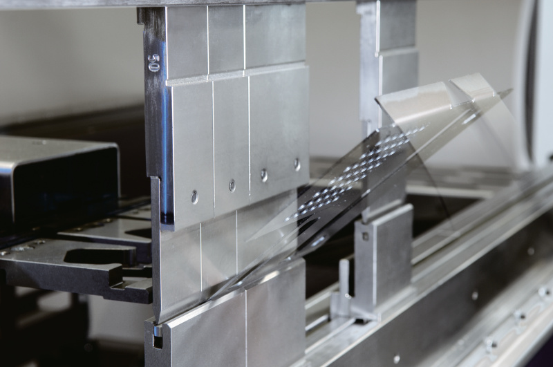
 A schematic of air bending with a backgauge.
There are three basic types of bending on a press brake, each is defined by the relationship of the end tool position to the thickness of the material. These three are Air Bending, Bottoming and Coining. The configuration of the tools for these three types of bending are nearly identical. A die with a long rail form tool with a radiused tip that locates the inside profile of the bend is called a punch. Punches are usually attached to the ram of the machine by clamps and move to produce the bending force. A die with a long rail form tool that has concave or V shaped lengthwise channel that locate the outside profile of the form is called a die. Dies are usually stationary and located under the material on the bed of the machine. Note that some locations do not differentiate between the two different kinds of dies (punches and dies.) The other types of bending listed use specially designed tools or machines to perform the work.
Air bending
This bending method forms material by pressing a punch (also called the upper or top die) into the material, forcing it into a bottom V-die, which is mounted on the press. The punch forms the bend so that the distance between the punch and the side wall of the V is greater than the material thickness (T).
Either a V-shaped or square opening may be used in the bottom die (dies are frequently referred to as tools or tooling). A set of top and bottom dies are made for each product or part produced on the press. Because it requires less bend force, air bending tends to use smaller tools than other methods.
Some of the newer bottom tools are adjustable, so, by using a single set of top and bottom tools and varying press-stroke depth, different profiles and products can be produced. Different materials and thicknesses can be bent in varying bend angles, adding the advantage of flexibility to air bending. There are also fewer tool changes, thus, higher productivity.[2]
A disadvantage of air bending is that, because the sheet does not stay in full contact with the dies, it is not as precise as some other methods, and stroke depth must be kept very accurate. Variations in the thickness of the material and wear on the tools can result in defects in parts produced.[2]
Air bending's angle accuracy is approximately ±0.5 deg. Angle accuracy is ensured by applying a value to the width of the V opening, ranging from 6 T (six times material thickness) for sheets to 3 mm thick to 12 T for sheets more than 10 mm thick. Springback depends on material properties, influencing the resulting bend angle.[2]
Depending on material properties, the sheet may be overbended to compensate for springback.[3]
Air bending does not require the bottom tool to have the same radius as the punch. Bend radius is determined by material elasticity rather than tool shape.[2]
The flexibility and relatively low tonnage required by air bending are helping to make it a popular choice. Quality problems associated with this method are countered by angle-measuring systems, clamps and crowning systems adjustable along the x and y axes, and wear-resistant tools.[2]
The K-Factor approximations given below are more likely to be accurate for air bending than the other types of bending due to the lower forces involved in the forming process.
Bottoming
In bottoming, the sheet is forced against the V opening in the bottom tool. U-shaped openings cannot be used. Space is left between the sheet and the bottom of the V opening. The optimum width of the V opening is 6 T (T stands for material thickness) for sheets about 3 mm thick, up to about 12 T for 12 mm thick sheets. The bending radius must be at least 0.8 T to 2 T for sheet steel. Larger bend radius require about the same force as larger radii in air bending, however, smaller radii require greater force—up to five times as much—than air bending. Advantages of bottoming include greater accuracy and less springback. A disadvantage is that a different tool set is needed for each bend angle, sheet thickness, and material. In general, air bending is the preferred technique.[2]
Coining
In coining, the top tool forces the material into the bottom die with five to 30 times the force of air bending, causing permanent deformation through the sheet. There is little, if any, springback. Coining can produce an inside radius is as low as 0.4 T, with a 5 T width of the V opening. While coining can attain high precision, higher costs mean that it is not often used.[2]
Three-point bending
Three-point bending is a newer process that uses a die with an adjustable-height bottom tool, moved by a servo motor. The height can be set within 0.01 mm. Adjustments between the ram and the upper tool are made using a hydraulic cushion, which accommodates deviations in sheet thickness. Three-point bending can achieve bend angles with 0.25 deg. precision. While three-point bending permits high flexibility and precision, it also entails high costs and there are fewer tools readily available. It is being used mostly in high-value niche markets.[2]
Folding
In folding, clamping beams hold the longer side of the sheet. The beam rises and folds the sheet around a bend profile. The bend beam can move the sheet up or down, permitting the fabricating of parts with positive and negative bend angles. The resulting bend angle is influenced by the folding angle of the beam, tool geometry, and material properties. Large sheets can be handled in this process, making the operation easily automated. There is little risk of surface damage to the sheet.[2]
Wiping
In wiping, the longest end of the sheet is clamped, then the tool moves up and down, bending the sheet around the bend profile. Though faster than folding, wiping has a higher risk of producing scratches or otherwise damaging the sheet, because the tool is moving over the sheet surface. The risk increases if sharp angles are being produced. Wiping on press brakes involves special tools.[2]
This method will typically bottom or coin the material to set the edge to help overcome springback. In this bending method, the radius of the bottom die determines the final bend radius.
Rotary bending
Rotary bending is similar to wiping but the top die is made of a freely rotating cylinder with the final formed shape cut into it and a matching bottom die. On contact with the sheet, the roll contacts on two points and it rotates as the forming process bends the sheet. This bending method is typically considered a "non-marking" forming process suitable to pre-painted or easily marred surfaces. This bending process can produce angles greater than 90° in a single hit on standard press brakes or flat presses.
Roll bending
 Roll bendingMain article: Roll bending
The roll bending process induces a curve into bar or plate workpieces.
Elastomer bending
In this method, the bottom V-die is replaced by a flat pad of urethane or rubber. As the punch forms the part, the urethane deflects and allows the material to form around the punch. This bending method has a number of advantages. The urethane will wrap the material around the punch and the end bend radius will be very close to the actual radius on the punch. It provides a non-marring bend and is suitable for pre-painted or sensitive materials. Using a special punch called a radius ruler with relieved areas on the urethane U-bends greater than 180° can be achieved in one hit, something that is not possible with conventional press tooling. Urethane tooling should be considered a consumable item and while they are not cheap , they are a fraction of the cost of dedicated steel tooling. It also has some drawbacks, this method requires tonnage similar to bottoming and coining and does not do well on flanges that are irregular in shape, that is where the edge of the bent flange is not parallel to the bend and is short enough to engage the urethane pad.
Joggling
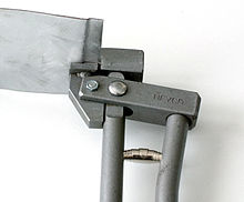 A joggle bend in sheet metal and a joggling tool
Joggling,[4] also known as joggle bending, is an offset bending process in which the two opposite bends are each greater than 90°, and are separated by a neutral web less than 5 workpiece thicknesses apart.[5]
Calculations
Many variations of these formulas exist and are readily available online. These variations may often seem to be at odds with one another, but they are invariably the same formulas simplified or combined. What is presented here are the unsimplified formulas. All formulas use the following keys:
- BA = bend allowance
- BD = bend deduction
- R = inside bend radius
- K = K-Factor, which is t / T
- T = material thickness
- t = distance from inside face to the neutral line[6]
- A = bend angle in degrees (the angle through which the material is bend)
The neutral line (also called the neutral axis) is an imaginary line that can be drawn through the cross-section of the workpiece that represents the lack of any internal forces. Its location in the material is a function of the forces used to form the part and the material yield and tensile strengths.
Both bend deduction and bend allowance represent the difference between the neutral line or unbent flat pattern (the required length of the material prior to bending) and the formed bend. Subtracting them from the combined length of both flanges gives the flat pattern length. The question of which formula to use is determined by the dimensioning method used to define the flanges as shown in the two diagrams below.
Bend allowance
The bend allowance (BA) is the length of the arc of the neutral line between the tangent points of a bend in any material. Adding the length of each flange taken between the center of the radius to the BA gives the Flat Pattern length. This bend allowance formula is used to determine the flat pattern length when a bend is dimensioned from 1) the center of the radius, 2) a tangent point of the radius or 3) the outside tangent point of the radius on an acute angle bend.
The BA can be calculated using the following formula:[7]
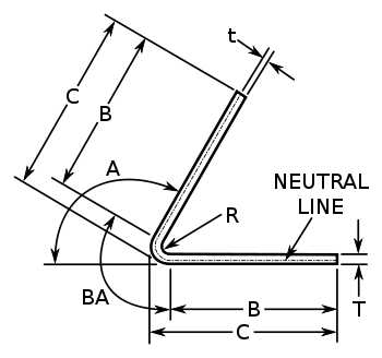 Diagram showing standard dimensioning scheme when using Bend Allowance formulas. Note that when dimensions "C" are specified, dimension B = C - R - T
Bend deduction
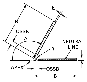 Diagram showing standard dimensioning scheme when using Bend Deduction formulas.
The outside set back (OSSB) is the length from the tangent point of the radius to the apex of the outside of the bend. The bend deduction (BD) is twice the outside setback minus the bend allowance. BD is calculated using the following formula:[8]
K-factor
K-factor is a ratio of location of the neutral line to the material thickness as defined by t/T where t = location of the neutral line and T = material thickness. The K-Factor formulation does not take the forming stresses into account but is simply a geometric calculation of the location of the neutral line after the forces are applied and is thus the roll-up of all the unknown (error) factors for a given setup. The K-factor depends on many factors including the material, the type of bending operation (coining, bottoming, air-bending, etc.) the tools, etc. and is typically between 0.3 to 0.5.
The following equation relates the K-factor to the bend allowance:[9]
The following table is a "Rule of Thumb". Actual results may vary remarkably.
Generic K-Factors Aluminum Steel Radius Soft Materials Medium Materials Hard Materials Air Bending 0 to Thickness 0.33 0.38 0.40 Thickness to 3 x Thickness 0.40 0.43 0.45 Greater than 3 x Thickness 0.50 0.50 0.50 Bottoming 0 to Thickness 0.42 0.44 0.46 Thickness to 3 x Thickness 0.46 0.47 0.48 Greater than 3 x Thickness 0.50 0.50 0.50 Coining 0 to Thickness 0.38 0.41 0.44 Thickness to 3 x Thickness 0.44 0.46 0.47 Greater than 3 x Thickness 0.50 0.50 0.50 The following formula can be used in place of the table as a good approximation of the K-Factor for Air Bending:
LOG(MIN(100,MAX(20 × R,T) / T)) / LOG(100) / 2
Material considerations
Material sheet thickness varies from 1/32 to ½ in with length from 6 in to 20 ft. Ductile materials are best suited for the pressing like aluminum, mild steel and new plastic materials.[1]
Advantages
Bending is a cost effective process when used for low to medium quantities, because it does not require significant amounts of tooling.[1]
See also
- Press brake
- Brake (sheet metal bending)
References
- ^ a b c d e Manufacturing Processes Reference Guide, Industrial Press Inc., 1994.
- ^ a b c d e f g h i j F., M. (August 2008), "Press Brake Bending: Methods and Challenges", Metalforming: 38–43, http://archive.metalformingmagazine.com/2008/08/Press_Brake_Bending.pdf.
- ^ Tool and Manufacturing Engineers Handbook, Volume 2, Forming, 4th Edition, Society of Manufacturing Engineers, 1984
- ^ 3-81. DRAW FORMING
- ^ http://www.toolingu.com/definition-410130-35505-joggle-bend.html
- ^ http://www.ciri.org.nz/bendworks/bending.pdf
- ^ How to Calculate Bend Allowance for Your Press Brake, archived from the original on 2010-02-24, http://www.webcitation.org/5nmuupS8L, retrieved 2010-02-24.
- ^ Sheet metal bend deduction, archived from the original on 2010-02-24, http://www.webcitation.org/5nmuYx6gW, retrieved 2010-02-24.
- ^ Diegel, Olaf (July 2002), BendWorks, archived from the original on 2010-02-24, http://www.webcitation.org/5nmu2Ljx7, retrieved 2010-02-24.
Bibliography
- Benson, Steve D. Press Brake Technology: A Guide to Precision Sheet Metal Bending. Society of Manufacturing Engineers, 1997. ISBN 978-0872634831
- Todd, Robert H.; Allen, Dell K.; Alting, Leo (1994), Manufacturing Processes Reference Guide, Industrial Press Inc., ISBN 0-8311-3049-0, http://books.google.com/books?id=6x1smAf_PAcC.
External links
- Latang, Paul. "Bending Made Easy" Fabricating & Metalworking, February 2010.
Categories:- Metal forming
- Fabrication (metal)


Wikimedia Foundation. 2010.