- NMOS logic
-
N-type metal-oxide-semiconductor logic uses n-type metal-oxide-semiconductor field effect transistors (MOSFETs) to implement logic gates and other digital circuits. NMOS transistors have four modes of operation: cut-off (or sub-threshold), triode, saturation (sometimes called active), and velocity saturation.
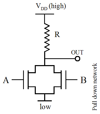
The n-type MOSFETs are arranged in a so-called "pull-down network" (PDN) between the logic gate output and negative supply voltage, while a resistor is placed between the logic gate output and the positive supply voltage. The circuit is designed such that if the desired output is low, then the PDN will be active, creating a current path between the negative supply and the output.
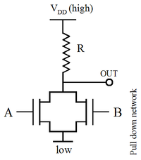
As an example, here is a NOR gate in NMOS logic. If either input A or input B is high (logic 1, = True), the respective MOS transistor acts as a very low resistance between the output and the negative supply, forcing the output to be low (logic 0, = False). When both A and B are high, both transistors are conductive, creating an even lower resistance path to ground. The only case where the output is high is when both transistors are off, which occurs only when both A and B are low, thus satisfying the truth table of a NOR gate:
A B A NOR B 0 0 1 0 1 0 1 0 0 1 1 0 A MOSFET can be made to operate as a resistor, so the whole circuit can be made with n-channel MOSFETs only. For many years, this made NMOS circuits much faster than comparable PMOS and CMOS circuits, which had to use much slower p-channel transistors. It was also easier to manufacture NMOS than CMOS, as the latter has to implement p-channel transistors in special n-wells on the p-substrate. The major problem with NMOS (and most other logic families) is that a DC current must flow through a logic gate even when the output is in a steady state (low in the case of NMOS). This means static power dissipation, i.e. power drain even when the circuit is not switching. This is a similar situation to the modern high speed, high density CMOS circuits (microprocessors etc.) which also has significant static current draw, although this is due to leakage, not bias. However, older and/or slower static CMOS circuits used for ASICs, SRAM etc., typically have very low static power consumption.
Also, NMOS circuits are slow to transition from low to high. When transitioning from high to low, the transistors provide low resistance, and the capacitative charge at the output drains away very quickly (similar to discharging a capacitor through a very low resistor). But the resistance between the output and the positive supply rail is much greater, so the low to high transition takes longer (similar to charging a capacitor through a high value resistor). Using a resistor of lower value will speed up the process but also increases static power dissipation. However, a better (and the most common) way to make the gates faster is to use depletion-mode transistors instead of enhancement-mode transistors as loads. This is called depletion-load NMOS logic.
Additionally, just like in DTL, TTL and ECL etc., the asymmetric input logic levels make NMOS circuits somewhat susceptible to noise. These disadvantages are why the CMOS logic now has supplanted most of these types in most high-speed digital circuits such as microprocessors (despite the fact that CMOS was originally very slow).
See also
- PMOS logic
- Depletion-load NMOS logic (including the processes called HMOS (high density, short channel MOS), HMOS-II, HMOS-III, etc. A family of high performance manufacturing processes for depletion-load NMOS logic circuits that was developed by Intel in the late 1970s and used for many years. Several CMOS manufacturing processes such as CHMOS, CHMOS-II, CHMOS-III, etc., descended directly from these NMOS-processes.
Logic families Technologies BiCMOS · CMOS · Depletion-load NMOS logic (including HMOS) · Diode logic · Diode–transistor logic (DTL) · Direct-coupled transistor logic (DCTL) · Emitter-coupled logic (ECL) · Gunning transceiver logic (GTL) · Integrated injection logic (I2L) · NMOS logic · PMOS logic · Resistor–transistor logic (RTL) · Transistor–transistor logic (TTL)
Types Static · Dynamic · Domino logic · Four-phase logic
Categories:- Logic families
Wikimedia Foundation. 2010.