- Phase contrast microscopy
-
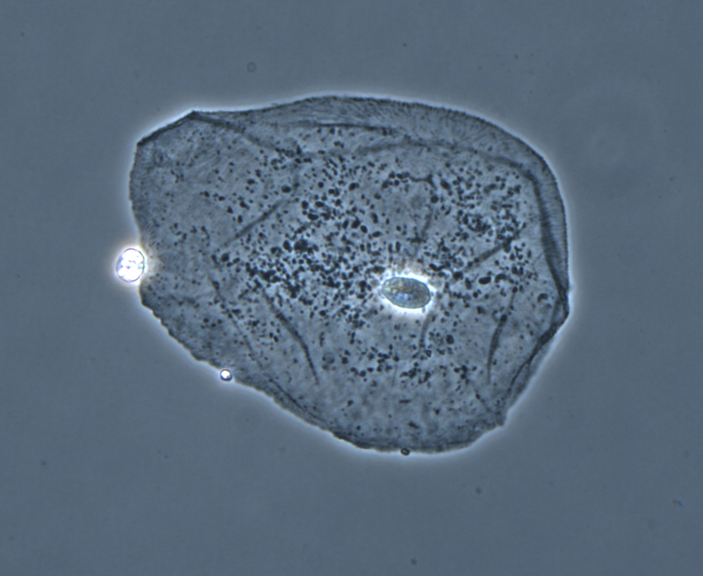
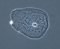 Phase contrast image of a cheek epithelial cell
Phase contrast microscopy is an optical microscopy illumination technique of great importance to biologists in which small (invisible to the human eye) phase shifts in the light passing through a transparent specimen are converted into (visible) amplitude or contrast changes in the image.
A phase contrast microscope does not require staining to view the slide. This type of microscope made it possible to study the cell cycle.
When light travels through a medium other than vacuum, interaction with this medium causes its amplitude and phase to change in a way which depends on properties of the medium. Changes in amplitude arise from absorption of light, which is often wavelength dependent and may give rise to colours. The human eye measures only the energy of light arriving on the retina, so changes in phase are not easily observed under optimal bright field illumination, yet often these changes in phase carry much important information.
The same situation applies in a typical microscope with "Kohler" bright-field illumination, i.e., although the phase variations introduced by the sample are preserved by the instrument (at least within the instrumental limits of imaging perfection) this information is lost in the process öf image recording, which measures only light intensity. In order to make phase variations observable, it is necessary to combine the light passing through the sample with a reference so that the resulting interference reveals the phase structure of the sample.
This problem was first appreciated by Frits Zernike during his study of diffraction gratings. During the course of his work he realised that it is necessary both to achieve interference with a reference beam, and (for maximizing the contrast achieved with the technique) to introduce a phase shift to this reference beam so that the no-phase-change condition gives rise to completely destructive interference.
He later realized that the same technique can be applied to optical microscopy. The necessary phase shift is introduced by rings etched accurately onto glass plates so that they introduce the required phase shift when inserted into the optical path of the microscope. When in use, this technique allows the phase of the light passing through the object under study to be inferred from the intensity of the image produced by the microscope. This methodology is known as the phase-contrast technique.
In optical microscopy many biological objects such as cell components in protozoans, bacteria and sperm tails are fully transparent unless stained. (Staining is a difficult and time-consuming procedure which can destroy or alter the specimen sructure). The difference in densities and composition within the imaged objects however often give rise to changes in the phase of light passing through them, hence they are sometimes called "phase objects". Using the phase-contrast technique makes these structures visible and allows their study in living specimens.
This phase contrast technique proved to be such an advancement in microscopy that Zernike was awarded the Nobel prize (physics) in 1953.
Contents
Background
The technique was invented by Frits Zernike in the 1930s for which he received the Nobel prize in physics in 1953. Phase-contrast is an imaging mode available on most advanced light microscopes and is most commonly used to provide contrast of transparent specimens such as living cells or small organisms.
Description
A practical implementation of phase-contrast illumination consists of a phase ring (located in an aperture plane located somewhere behind the front lens element of the objective) and a matching annular ring, which is located in the conjugate primary aperture plane (location of the condenser's aperture).
Two selected light rays, which are emitted from one point inside the lamp's filament, are focused by the field lens exactly inside the opening of the condenser annular ring. Since this location is precisely in the front focal plane of the condenser, the two light rays are then refracted in such way that they exit the condenser as parallel rays. Assuming that the two rays in question are neither refracted nor diffracted in the specimen plane (location of microscope slide), they enter the objective as parallel rays. Since all parallel rays are focused in the back focal plane of the objective, the back focal plane is a conjugate aperture plane to the condenser's front focal plane (also location of the condenser annulus). To complete the phase setup, a phase plate is positioned inside the back focal plane in annulus.
Only through correctly centering the two elements can phase contrast illumination be established. A phase centering telescope that temporarily replaces one of the oculars can be used, first to focus the phase element plane and then center the annular illumination ring with the corresponding ring of the phase plate. In some microscopes models, an in-built Bertrand lens serves the same purpose as the telescope.
An interesting variant in phase contrast design was once implemented (by the microscope maker C. Baker, London) in which the conventional annular form of the two elements was replaced by a cross-shaped transmission slit in the substage and corresponding cross-shaped phase plates in the conjugate plane in the objectives. The advantage claimed here was that only a single slit aperture was needed for all phase objective magnifications. Recentring and rotational alignment of the cross by means of the telescope was nevertheless needed for each change in magnification.
Image appearance
Phase contrast images have a characteristic grey background with light and dark features found across the sample. Light and dark fringes appear around regions with a change in optical density, for example the boundary between water and a cell. This normally manifests itself as a bright halo around a dark object.
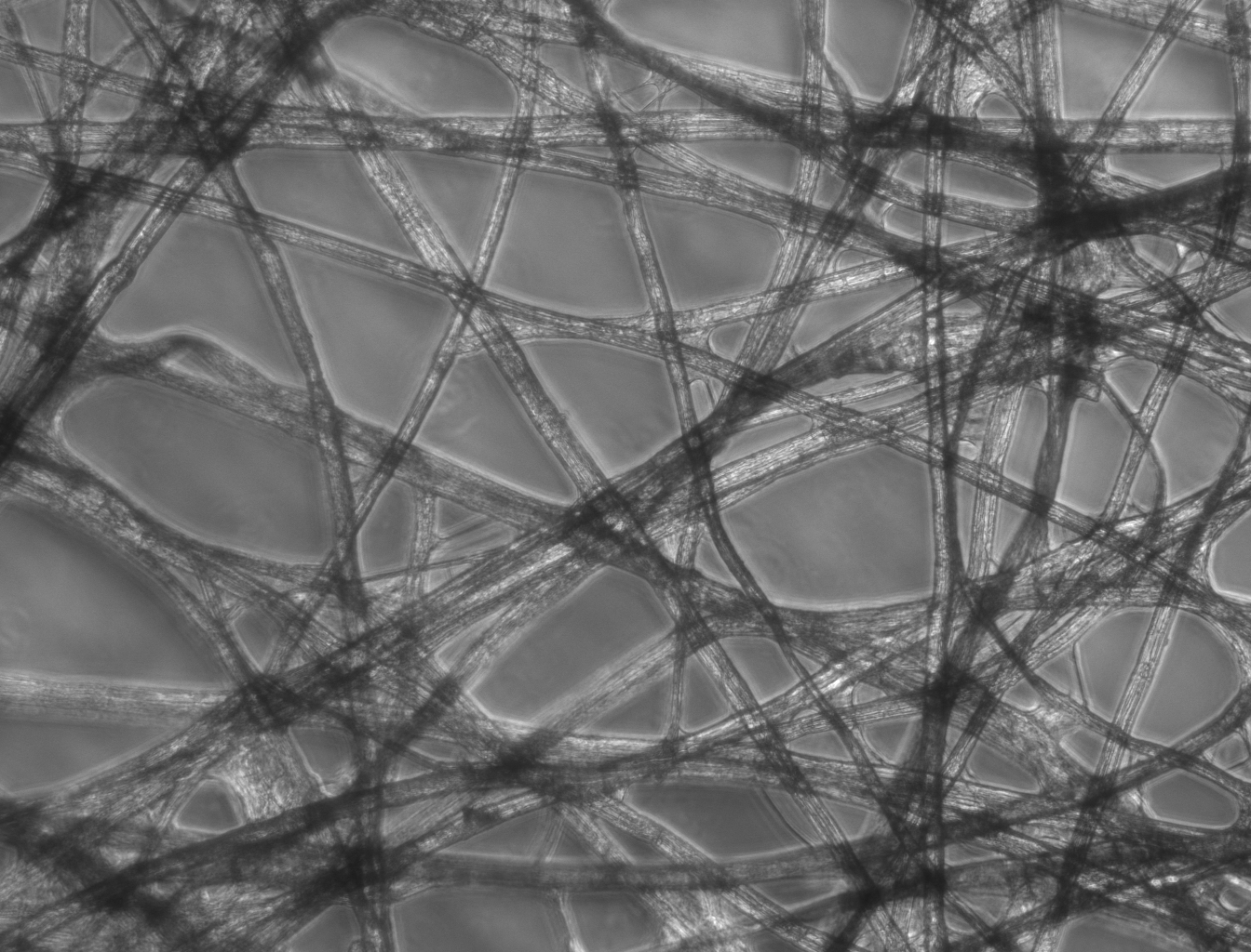
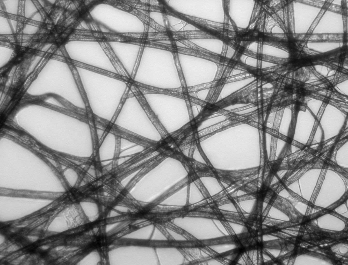
- Comparison of transilumination techniques used to generate contrast in a sample of tissue paper. 1.559 μm/pixel.
-

Phase contrast illumination, sample contrast comes from interference of different path lengths of light through the sample.
-

Bright field illumination, sample contrast comes from absorbance of light in the sample.
-
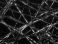
Cross-polarized light illumination, sample contrast comes from rotation of polarized light through the sample.
-
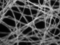
Dark field illumination, sample contrast comes from light scattered by the sample.
Technical details
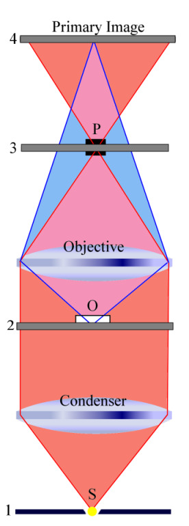
 1. Condenser annulus
2. Object plane
3. Phase plate
4. Primary image planeTo understand how phase contrast illumination works, we study two wave fronts (see the figure to the right). This figure simplifies a few things. First, the condenser annulus is just a small aperture located in the center (see the plane labeled '1') and the phase plate is also just covering a small aperture (located in the plane labeled '3'). Second, the optical system is greatly simplified by showing only two single lenses to represent all optical elements.
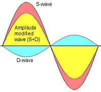 D-wave and S-wave
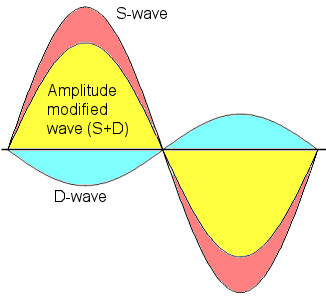
The plane labeled '1' is the front focal plane of the condenser. The light emanating from the small aperture 'S' is captured by the condenser and emerges as light with only parallel wavefronts from the condenser. When these plane waves (parallel wave fronts) hit the phase object 'O' (located in the object plane labeled '2'), some of this light is diffracted (and/or refracted) while moving through the specimen. Assuming that the specimen does not significantly alter the amplitudes of the incoming wavefronts but mainly changes phase relations with respect to the "unperturbed" wavefronts, newly generated spherical wave fronts that are retarded by 90° (λ/4) emanate from 'O' (see the purple area that contains now "unperturbed" plane waves and spherical wave fronts). It is important to note that there are now two types of waves, the surround wave or S-wave and the diffracted wave or D-wave, which have a relative phase-shift of 90° (λ/4). - The objective focuses the D-wave inside the primary image plane (labeled '4'), while it focuses the S-wave inside the back focal plane (labeled '3'). The location of the phase plate 'P' has now a profound impact on the S-wave while leaving most of the D-wave "unharmed". In what is known as positive phase contrast optics, the phase plate 'P' reduces the amplitude of all light rays traveling through the phase annulus (mainly S-waves) by 70 to 90% and advances the phase by yet another 90° (λ/4). However, the phase plate leaves most of the D-waves "untouched". Hence the recombination of these two waves (D + S) in the primary image plane (labeled '4') results in a significant amplitude change at all locations where there is a now destructive interference due to a 180° (λ/2) phase shifted D-wave. The net phase shift of 180° (λ/2) results directly from the 90° (λ/4) retardation of the D-wave due to the phase object and the 90° (λ/4) phase advancement of the S-wave due to the phase plate. Without the phase plate, there would be no significant destructive interference that greatly enhances contrast. With phase contrast illumination "invisible" phase variations are hence translated into visible amplitude variations. The destructive interference is illustrated in the figure to the left. Blue and orange indicate D-wave and S-wave, respectively. The resulting wave (D + S), indicated by yellow, has a reduced amplitude.
Implementing phase contrast function using a 4F correlator
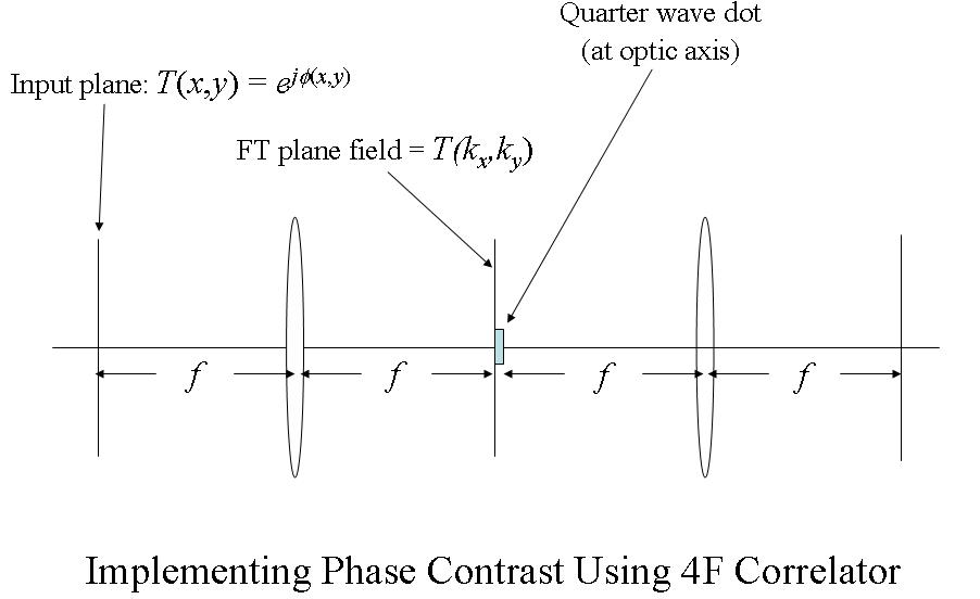
We can see how the phase contrast principle works by considering the figure below, which shows a 4F correlator (see Fourier optics) that implements the phase contrast function (in this figure, magnification is unity, so it cannot really be called a microscope in the usual sense).
 Implementing phase contrast using a 4F correlator
With reference to this figure, we assume a plane wave incident from the left and a phase transmittance function of the form:

The term, φ(x,y) in the exponent is known as the phase (see phase (waves)) of the transmittance function. If this "phase object" is thin, so that ϕ(x,y) < < 1 then,

Film (or detectors) respond to variations in amplitude, not phase. The transmittance function above will have very small variations in amplitude, since the two terms in the transmittance function are in phase quadrature. For maximum contrast, we will prefer to have these two terms in-phase (not in quadrature phase), so that variations in ϕ(x,y) directly impact the amplitude of the transmittance function. We accomplish this by selectively multiplying one term in the equation above by a factor of j, thus bringing the two terms in-phase.
We can accomplish this using the 4F correlator in the following way. We assume a plane wave field incident on the "input plane" of the correlator (on the far left in the diagram). The Fourier transform (FT) of the phase transmittance function

is formed in the back focal plane of the first lens as

where PSF(kx,ky) is the Point spread function (PSF) of the lens. The PSF is basically just a small dot in the FT plane (the back focal plane of the first lens), whereas the function Φ(kx,ky) will be more spread out. Since the PSF is localized to a small region about the optic axis (the horizontal axis) in the FT plane, we may place a small, quarter-wavelength thick dot there. This dot will impart a quarter wavelength phase shift to the PSF(kx,ky) term, while leaving the Φ(kx,ky) term relatively unaffected.
So, behind the dot, the field has the form:

and both terms are now in-phase. We now FT this field distribution using the second lens, to produce the following field in the "output plane" (the rightmost plane) of the 4F correlator system:

where we now neglect the factor of j common to both terms. Now the phase function, ϕ(x,y) directly modulates transmittance amplitude, making for better contrast in the images.
See also
References
- Bennett, A., Osterberg, H, Jupnik, H. and Richards, O., Phase Microscopy: Principles and Applications, John Wiley and Sons, Inc., New York, 320 pages (1951).
- Murphy, Douglas B Fundamentals of Light Microscopy and Electronic Imaging, John Wiley & Sons (2001)
- Pluta, Maksymilian, Advanced Light Microscopy, Vol 2, Specialized Methods, Elsevier and PWN-Polish Scientific Publishers (1989)
- Zernike, F., Phase-contrast, a new method for microscopic observation of transparent objects. Part I.., Physica: 9, 686-698 (1942).
- Zernike, F., Phase-contrast, a new method for microscopic observation of transparent objects. Part II.., Physica: 9, 974-986 (1942).
- Zernike, F., How I discovered phase contrast., Science: 121, 345-349 (1955).
- References
External links
- The Phase Contrast Microscope
- Phase Contrast Illumination
- Molecular Expressions: Phase Contrast Microscopy
- Microscopy University: Principles of Phase Contrast Microscopy
- Microscopy University: Principles of Phase Contrast Microscopy: Phase contrast microscopy
Illumination and
contrast methods
Fluorescence methods Fluorescence microscopy · Confocal microscopy · Two-photon excitation microscopy · Multiphoton microscopy · Image deconvolution · Total internal reflection fluorescence microscopy (TIRF)Sub-diffraction
limit techniquesDiffraction limit · Stimulated emission depletion (STED) · Photo-activated localization microscopy (PALM) · Near-field (NSOM/SNOM)Categories:- Microscopy
- Microscopes


Wikimedia Foundation. 2010.