- History of radar
-
The history of radar starts with experiments by Heinrich Hertz in the late 19th century that showed that radio waves were reflected by metallic objects. This possibility was suggested in James Clerk Maxwell's seminal work on electromagnetism. However, it was not until the early 20th century that systems able to use these principles were becoming widely available, and it was German engineer Christian Huelsmeyer who first used them to build a simple ship detection device intended to help avoid collisions in fog (Reichspatent Nr. 165546). Numerous similar systems were developed over the next two decades.
The name radar comes from the acronym RADAR, coined in 1940 by the U.S. Navy for public reference to their highly classified work in Radio Detection And Ranging. Thus, a true radar system must both detect and provide range (distance) information for a target. Before 1934, no single system gave this performance; some systems were omni-directional and provided ranging information, while others provided rough directional information but not range. A key development was the use of pulses that were timed to provide ranging, which were sent from large antennas that provided accurate directional information. Combining the two allowed for accurate plotting of targets.
Contents
Worldwide differential in antecedence
In the 1934–1939 period, eight nations developed, independently and in great secrecy, systems of this type: the United States, Great Britain, Germany, the USSR, Japan, the Netherlands, France, and Italy. In addition, Great Britain had shared their basic information with four Commonwealth countries: Australia, Canada, New Zealand, and South Africa, and these countries had also developed indigenous radar systems. During the war, Hungary was added to this list.[1]
Progress during the war was rapid and of great importance, probably one of the decisive factors for the victory of the Allies. By the end of hostilities, the United States, Great Britain, Germany, the USSR, and Japan had a wide diversity of land- and sea-based radars as well as small airborne systems. After the war, radar use was widened to numerous fields including: civil aviation, marine navigation, radar guns for police, meteorology and even medicine.
Significance
The place of radar in the larger story of science and technology is argued differently by different authors. On the one hand, radar contributed very little to theory, which was largely known since the days of Maxwell and Hertz. Therefore radar did not advance science, but was simply a matter of technology and engineering. Maurice Ponte, one of the developers of radar in France, states:
- Le principe fondamental du radar appartient au patrimoine commun des physiciens : ce qui demeure en fin de compte au crédit réel des techniciens se mesure à la réalisation effective de matériels opérationnels.,[2] or roughly
- The fundamental principle of the radar belongs to the common patrimony of the physicists : after all, what is left to the real credit of the technicians is measured by the effective realisation of operational materials.
But others point out the immense practical consequences of the development of radar. Far more than the atomic bomb, radar contributed to Allied victory in World War II.[3] Robert Buderi[4] states that it was also the precursor of much modern technology. From a review of his book:
. . . radar has been the root of a wide range of achievements since the war, producing a veritable family tree of modern technologies. Because of radar, astronomers can map the contours of far-off planets, physicians can see images of internal organs, meteorologists can measure rain falling in distant places, air travel is hundreds of times safer than travel by road, long-distance telephone calls are cheaper than postage, computers have become ubiquitous and ordinary people can cook their daily dinners in the time between sitcoms, with what used to be called a radar range.[5]
Early Contributors
Heinrich Hertz
In 1887 the German physicist Heinrich Hertz (1857–1894) began experimenting with electromagnetic waves in his laboratory. He found that these waves could be transmitted through different types of materials, and were reflected by others, such as conductors and dielectrics. The existence of electromagnetic waves was predicted earlier by the Scottish physicist James Clerk Maxwell (1831–79), but it was Hertz who first succeeded in generating and detecting what were soon called radio waves.
Guglielmo Marconi
The development of the wireless or radio is often attributed to Guglielmo Marconi (1874–1937). Although he was not the first to "invent" this technology, it might be said that he was the greatest early promoter of practical radio systems and their applications. In a paper read before the Institution of Electrical Engineers in London on March 3, 1899, Marconi described radio beacon experiments he had conducted in Salisbury Plain. Concerning this lecture, in a 1922 paper he wrote:
- I also described tests carried out in transmitting a beam of reflected waves across country . . . and pointed out the possibility of the utility of such a system if applied to lighthouses and lightships, so as to enable vessels in foggy weather to locate dangerous points around the coasts...
- It [now] seems to me that it should be possible to design [an] apparatus by means of which a ship could radiate or project a divergent beam of these rays in any desired direction, which rays, if coming across a metallic object, such as another steamer or ship, would be reflected back to a receiver screened from the local transmitter on the sending ship, and thereby immediately reveal the presence and bearing of the other ship in fog or thick weather.[6]
This paper and a speech presenting the paper to a joint meeting of the Institute of Radio Engineers and the American Institute of Electrical Engineers in New York City on June 20, 1922, is often cited as the seminal event which began widespread interest in the development of radar.[7]
Christian Huelsmeyer
In 1904 Christian Huelsmeyer (1881–1957) gave public demonstrations in Germany and the Netherlands of the use of radio echoes to detect ships so that collisions could be avoided. His device consisted of a simple spark gap used to generate a signal that was aimed using a dipole antenna with a cylindrical parabolic reflector. When a signal reflected from a ship was picked up by a similar antenna attached to the separate coherer receiver, a bell sounded. During bad weather or fog, the device would be periodically "spun" to check for nearby ships. The apparatus detected presence of ships up to 3 km, and Huelsmeyer planned to extend its capability to 10 km. It did not provide range (distance) information, only warning of a nearby object. He patented the device, called the telemobiloscope, but due to lack of interest by the naval authorities the invention was not put into production.[8]
Huelsmeyer also received a patent amendment for estimating the range to the ship. Using a vertical scan of the horizon with the telemobiloscope mounted on a tower, the operator would find the angle at which the return was the most intense and deduce, by simple triangulation, the approximate distance. This is in contrast to the later development of pulsed radar, which determines distance directly.
Nikola Tesla
One of the hundreds of concepts generated by Nikola Tesla (1856–1943) included principles regarding frequency and power levels for primitive radio-location units. In an interview published in The Electrical Experimenter, August 1917, Tesla gave the following:
- For instance, by their [standing electromagnetic waves] use we may produce at will, from a sending station, an electrical effect in any particular region of the globe; [with which] we may determine the relative position or course of a moving object, such as a vessel at sea, the distance traversed by the same, or its speed.[9]
Tesla also proposed the use of these standing electromagnetic waves along with pulsed reflected surface waves to determine the relative position, speed, and course of a moving object and other modern concepts of radar. Tesla had first proposed that radio location techniques might help find submarines (for which it is not well-suited) with a fluorescent screen indicator.
United States
In the United States, both the Navy and Army needed means of remotely locating enemy ships and aircraft. In 1930, both services initiated the development of radio equipment that could meet this need. There was little coordination of these efforts; thus, they will be described separately.
In the autumn of 1922, Albert H. Taylor and Leo C. Young at the U.S. Naval Aircraft Radio Laboratory were conducting communication experiments when they noticed that a wooden ship in the Potomac River was interfering with their signals; in effect, they had demonstrated the first multistatic radar, a system that uses separated transmitting and receiving antennas and detects targets due to changes in the signal. In 1930, Lawrence A. Hyland working with Taylor and Young, now at the U.S. Naval Research Laboratory (NRL) in Washington, D.C., used a similar arrangement of radio equipment to detect a passing aircraft. This led to a proposal by Taylor for using this technique for detecting ships and aircraft.
A simple wave-interference apparatus can detect the presence of an object, but it cannot determine its location or velocity. That had to await the invention of pulsed radar, and later, additional encoding techniques to extract this information from a CW signal. When Taylor's group at the NRL were unsuccessful in getting interference radio accepted as a detection means, Young suggested trying pulsing techniques. This would also allow the direct determination of range to the target. The British and the American research groups were independently aware of the advantages of such an approach, but the problem was to develop the timing equipment to make it feasible.
Robert Morris Page was assigned by Taylor to implement Young's suggestion. Page designed a transmitter operating at 60 MHz and pulsed 10 μs in duration and 90 μs between pulses. In December 1934, the apparatus was used to detect a plane at a distance of one mile (1.6 km) flying up and down the Potomac. Although the detection range was small and the indications on the oscilloscope monitor were almost indistinct, it demonstrated the basic concept of a pulsed radar system.[10] Based on this, Page, Taylor, and Young are usually credited with building and demonstrating the world’s first true radar.
An important subsequent development by Page was the duplexer, a device that allowed the transmitter and receiver to use the same antenna without over-whelming or destroying the sensitive receiver circuitry. This also solved the problem associated with synchronization of separate transmitter and receiver antennas which is critical to accurate position determination of long-range targets.
The experiments with pulsed radar were continued, primarily in improving the receiver for handling the short pulses. In June 1936, the NRL's first prototype radar system, now operating at 28.6 MHz, was demonstrated to government officials, successfully tracking an aircraft at distances up to 25 miles (40 km). Their radar was based on low frequency signals, at least by today's standards, and thus required large antennas, making it impractical for ship or aircraft mounting.
Antenna size is inversely proportional to the operating frequency; therefore, the operating frequency of the system was increased to 200 MHz, allowing much smaller antennas. The frequency of 200 MHz was the highest possible with existing transmitter tubes and other components. The new system was successfully tested at the NRL in April 1937, That same month, the first sea-borne testing was conducted. The equipment was temporarily installed on the USS Leary, with a Yagi antenna mounted on a gun barrel for sweeping the field of view.
Based on success of the sea trials, the NRL further improved the system. Page developed the ring oscillator, allowing multiple output tubes and increasing the pulse-power to 15 kW in 5-µs pulses. A 20-by-23-foot (7.0 m), stacked-dipole “bedspring” antenna was used. In laboratory test during 1938, the system, now designated XAF, detected planes at ranges up to 100 miles (160 km). It was installed on the battleship USS New York for sea trials starting in January 1939, and became the first operational radio detection and ranging set in the U.S. fleet.
In May 1939, a contract was awarded to RCA for production. Designated CXAM, deliveries started in May 1940. The acronym RADAR was coined from "Radio Detection And Ranging" as a cover reference to this highly secret technology. One of the first CXAM systems was placed aboard the USS California, a battleship that was sunk in the Japanese attack on Pearl Harbor on December 7, 1941.
United States Army
As the Great Depression started, economic conditions led the U.S. Army Signal Corps to consolidate its widespread laboratory operations to Fort Monmouth, New Jersey. On June 30, 1930, these were designated the Signal Corps Laboratories (SCL) and Lt. Colonel (Dr.) William R. Blair was appointed the SCL Director.
Among other activities, the SCL was made responsible for research in the detection of aircraft by acoustical and infrared radiation means. Blair had performed his doctoral research in the interaction of electromagnet waves with solid materials, and naturally gave attention to this type of detection. Initially, attempts were made to detect infrared radiation, either from the heat of aircraft engines or as reflected from large searchlights with infrared filters, as well as from radio signals generated by the engine ignition.
Some success was made in the infrared detection, but little was accomplished using radio. In 1932, progress at the Naval Research Laboratory (NRL) on radio interference for aircraft detection was passed on to the Army. While it does not appear that any of this information was used by Blair, the SCL did undertake a systematic survey of what was then known throughout the world about the methods of generating, modulating, and detecting radio signals in the microwave region.
The SCL's first definitive efforts in radio-based target detection started in 1934 when the Chief of the Army Signal Corps, after seeing a microwave demonstration by RCA, suggested that radio-echo techniques be investigated. The SCL called this technique radio position-finding (RPF). Based on the previous investigations, the SCL first tried microwaves. During 1934 and 1935, tests of microwave RPF equipment resulted in Doppler-shifted signals being obtained, initially at only a few hundred feet distance and later greater than a mile. These tests involved a bi-static arrangement, with the transmitter at one end of the signal path and the receiver at the other, and the reflecting target passing through or near the path.
Blair was evidently not aware of the success of a pulsed system at the NRL in December 1934. In an internal 1935 note, Blair had commented:
- Consideration is now being given to the scheme of projecting an interrupted sequence of trains of oscillations against the target and attempting to detect the echoes during the interstices between the projections.
In 1936, W. Delmar Hershberger, SCL’s Chief Engineer at that time, started a modest project in pulsed microwave transmission. Lacking success with microwaves, Hershberger visited the NRL (where he had earlier worked) and saw a demonstration of their pulsed set. Back at the SCL, he and Robert H. Noyes built an experimental apparatus using a 75 watt, 110 MHz (2.73 m) transmitter with pulse modulation and a receiver patterned on the one at the NRL. A request for project funding was turned down by the War Department, but $75,000 for support was diverted from a previous appropriation for a communication project.
In October 1936, Paul E. Watson became the SCL Chief Engineer and led the project. A field setup near the coast was made with the transmitter and receiver separated by a mile. On December 14, 1936, the experimental set detected at up to 7 mi (11 km) range aircraft flying in and out of New York City.
Work then began on a prototype system. Ralph I. Cole headed receiver work and William S. Marks lead transmitter improvements. Separate receivers and antennas were used for azimuth and elevation detection. Both receiving and the transmitting antennas used large arrays of dipole wires on wooden frames. The system output was intended to aim a searchlight. The first demonstration of the full set was made on the night of May 26, 1937. A bomber was detected and then illuminated by the searchlight. The observers included the Secretary of War, Henry A. Woodring; he was so impressed that the next day orders were given for the full development of the system. Congress gave an appropriation of $250,000.
The frequency was increased to 200 MHz (1.5 m). The transmitter used 16 tubes in a ring oscillator circuit (developed at the NRL), producing about 75 kW peak power. Major James C. Moore was assigned to head the complex electrical and mechanical design of lobe switching antennas. Engineers from Western Electric and Westinghouse were brought in to assist in the overall development. Designated SCR-268, a prototype was successfully demonstrated in late 1938 at Fort Monroe, Virginia. Production of SCR-268 sets was started by Western Electric in 1939, and it entered service in early 1941.
Even before the SCR-268 entered service, it had been greatly improved. In a project led by Major (Dr.) Harold A. Zahl, two new configurations evolved – the SCR-270 (mobile) and the SCR-271 (fixed-site). Operation at 106 MHz (2.83 m) was selected, and a single water-cooled tube provided 8 kW (100 kW pulsed) output power. Westinghouse received a production contract, and started deliveries near the end of 1940.
The Army deployed five of the first SCR-270 sets around the island of Oahu in Hawaii. At 7:02 on the morning of December 7, 1941, one of these radars detected a flight of aircraft at a range of 136 miles (219 km) due north. The observation was passed on to an aircraft warning center where it was misidentified as a flight of U.S. bombers known to be approaching from the mainland. The alarm went unheeded, and at 7:48, the Japanese aircraft first struck at Pearl Harbor.
Great Britain
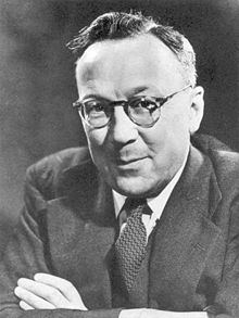 Robert Watson-Watt
In 1915, Robert Watson Watt joined the Meteorological Office as a meteorologist, working at an outstation at Aldershot in Hampshire. Over the next 20 years, he studied atmospheric phenomena and developed the use of radio signals generated by lightning strikes to map out the position of thunderstorms. The difficulty in pinpointing the direction of these fleeting signals led to the use of rotatable directional antennas, and in 1923 the use of oscilloscopes in order to display the signals. An operator would periodically rotate the antenna and look for "spikes" on the oscilloscope to find the direction of a storm. The operation eventually moved to the outskirts of Slough in Berkshire, and in 1927 formed the Radio Research Station (RRS), Slough, an entity under the Department of Scientific and Industrial Research (DSIR). Watson Watt was appointed the RSS Superintendent.
As war clouds gathered over Great Britain, the likelihood of air raids and the threat of invasion by air and sea drove a major effort in applying science and technology to defence. In November 1934, the Air Ministry established the Committee for Scientific Survey of Air Defence (CSSAD) with the official function of considering "how far recent advances in scientific and technical knowledge can be used to strengthen the present methods of defence against hostile aircraft." Commonly called the “Tizard Committee” after its Chairman, Sir Henry Tizard, this group had a profound influence on technical developments in Great Britain.
H. E. Wimperis, Director of Scientific Research at the Air Ministry and a member of the Tizard Committee, had read about Nikola Tesla's claim of inventing a 'death ray.'[11] Watson Watt, Superintendent of the RSS, Slough, was now well established as an authority in the field of radio, and in January 1935, Wimperis contacted him asking if radio might be used for such a device. After discussing this with his scientific assistant, Arnold F. 'Skip' Wilkins, Watson Watt wrote back that this was unlikely, but added the following comment: Attention is being turned to the still difficult, but less unpromising, problem of radio detection and numerical considerations on the method of detection by reflected radio waves will be submitted when required.
Over the following several weeks, Wilkins considered the radio detection problem. He outlined an approach and backed it with detailed calculations of necessary transmitter power, reflection characteristics of an aircraft, and needed receiver sensitivity. Watson Watt sent this information to the Air Ministry on February 12, 1935, in a secret report titled "The Detection of Aircraft by Radio Methods."
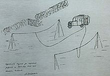 Sketch of the Daventry Experiment, 26 February 1935, set up by A.F.Wilkins to detect radio signals reflected from an aircraft.
Reflection of radio signals was critical to the proposed technique, and the Air Ministry asked if this could be proven. To test this, Wilkins set up receiving equipment in a field near Upper Stowe, Northamptonshire. On February 26, 1935, a Handley Page Heyford bomber flew along a path between the receiving station and the transmitting towers of a BBC shortwave station in nearby Daventry. The aircraft reflected the 6 MHz (49 m) BBC signal, and this was readily detected by Doppler-beat interference at ranges up to 8 mi (13 km). This convincing test, known as the Daventry Experiment, was witnessed by a representative from the Air Ministry, and led to the immediate authorization to build a full demonstration system.
Based on pulsed transmission as used for probing the ionosphere. a preliminary system was designed and built at the RRS by the team. Their existing transmitter had a peak power of about 1 kW, and Wilkins had estimated that 100 kW would be needed. Edward George Bowen was added to the team to design and build such a transmitter. Bowens’ transmitter operated at 6 MHz (50 m), had a pulse-repetition rate of 25 Hz, a pulse width of 25 μs, and approached the desired power.
Orfordness, a narrow, 19-mile (31 km) peninsula in Suffolk along the coast of the North Sea, was selected as the test site. Here the equipment would be openly operated in the guise of an ionospheric monitoring station. In mid-May, 1935, the equipment was moved to Orfordness. Six wooden towers were erected, two for stringing the transmitting antenna, and four for corners of crossed receiving antennas. In June, general testing of the equipment began.
On June 17, the first target was detected—a Supermarine Scapa flying boat at 17 mi (27 km) range.[12] It is historically correct that on June 17, 1935, radio-based detection and ranging was first demonstrated in Great Britain. Watson Watt, Wilkins, and Bowen are generally credited with initiating what would later be called radar in this nation.
In December 1935, the British Treasury appropriated £60,000 for a five-station system called Chain Home (CH), covering approaches to the Thames Estuary. The secretary of the Tizard Committee, Albert Percival Rowe, coined the acronym RDF as a cover for the work, meaning Range and Direction Finding but suggesting the already well-known Radio Direction Finding.
In 1940 John Randall (physicist) and Harry Boot developed the Cavity magnetron which made one centimeter radar a reality. This device, the size of a small dinner plate, could be carried easily on aircraft and the short wavelength meant that the antenna would also be small and hence suitable for mounting on aircraft. The short wavelength and high power made it very effective at spotting submarines from the air.
Air Ministry
In March 1936 the work at Orfordness was moved to Bawdsey Manor, nearby on the mainland. Until this time, the work had officially still been under the DSIR, but was now transferred to the Air Ministry. At the new Bawdsey Research Station, the CH equipment was assembled as a prototype. There were equipment problems when the Royal Air Force (RAF) first exercised the prototype station in September 1936. These were cleared by the next April, and the Air Ministry started plans for a larger network of stations.
Initial hardware at CH stations was as follows: The transmitter operated on four pre-selected frequencies between 20 and 55 MHz, adjustable within 15 seconds, and delivered a peak power of 200 kW. The pulse duration was adjustable between 5 to 25 μs, with a repetition rate selectable as either 25 or 50 Hz. For synchronization of all CH transmitters, the pulse generator was locked to the 50 Hz of the British power grid. Four 360-foot (110 m) steel towers supported transmitting antennas, and four 240-foot (73 m) wooden towers supported cross-dipole arrays at three different levels. A goniometer was used to improve the directional accuracy from the multiple receiving antennas.
By the summer of 1937, 20 initial CH stations were in check-out operation. A major RAF exercise was performed before the end of the year, and was such a success that £10,000,000 was appropriated by the Treasury for an eventual full chain of coastal stations. At the start of 1938, the RAF took over control of all CH stations, and the network began regular operations.
In May 1938, Rowe replaced Watson Watt as Superintendent at Bawdsey. In addition to the work on CH and successor systems, there was now major work in airborne RDF equipment. This was led by E. G. Bowen and centered on 200-MHz (1.5 m) sets. The higher frequency allowed smaller antennas, appropriate for aircraft installation.
From the initiation of RDF work at Orfordness, the Air Ministry had kept the British Army and the Royal Navy generally informed; this led to both of these forces having their own RDF developments.
British Army
In 1931, at the at the Woolwich Research Station of the Army’s Signals Experimental Establishment (SEE), W. A. S. Butement and P. E. Pollard had examined pulsed 600 MHz (50-cm) signals for detection of ships. Although they prepared a memorandum on this subject and performed preliminary experiments, for undefined reasons the War Office did not give it consideration.[13]
As the Air Ministry’s work on RDF progressed, Colonel Peter Worlledge of the Royal Engineer and Signals Board met with Watson Watt and was briefed on the RDF equipment and techniques being developed at Orfordness. His report, “The Proposed Method of Aeroplane Detection and Its Prospects,” led the SEE to set up an “Army Cell” at Bawdsey in October 1936. This was under E. Talbot Paris and the staff included Butement and Pollard. The Cell’s work emphasize two general types of RDF equipment: gun-laying (GL) systems for assisting anti-aircraft guns and searchlights, and coastal- defense (CD) systems for directing coastal artillery and defense of Army bases overseas.
Pollard led the first project, a gun-laying RDF code-named Mobile Radio Unit (MRU). This truck-mounted system was designed a small version of a CH station. It operated at 23 MHz (13 m) with a power of 300 kW. A single 105-foot (32 m) tower supported a transmitting antenna, as well as two receiving antennas set orthogonally for estimating the signal bearing. In February 1937, a developmental unit detected an aircraft at 60 m (96 km) range. The Air Ministry also adopted this system as a mobile auxiliary to the CH system.
In early 1938, Butement started the development of a CD system based on Bowen’s evolving 200-MHz (1.5-m) airborne sets. The transmitter had a 400 Hz pulse rate, a 2-μs pulse width, and 50 kW power (later increased to 150 kW). Although many of Bowen’s transmitter and receiver components were used, the system would not be airborne so there were no limitations on antenna size.
Primary credit for introducing beamed RDF systems in Great Britain must be given to Butement. For the CD, he developed a large dipole array, 10 feet (3.0 m) high and 24 feet (7.3 m) wide, giving much narrower beams and higher gain. This could be rotated at a speed up to 1.5 revolutions per minute. For greater directional accuracy, lobe switching on the receiving antennas was adopted. As a part of this development, he formulated the first – at least in Great Britain – mathematical relationship that would later become well known as the “radar range equation.”
By May 1939, the CD RDF could detect aircraft flying as low as 500 feet (150 m) and at a range of 25 mi (40 km). With an antenna 60 feet (18 m) above sea level, it could determine the range of a 2,000-ton ship at 24 mi (39 km) and with an angular accuracy of as little as a quarter of a degree.
Although the Royal Navy maintained close contact with the Air Ministry work at Bawdsey, they chose to establish their own RDF development at the Experimental Department of His Majesty’s Signal School (HMSS) in Portsmouth, Hampshire, on the south coast.
The HMSS started RDF work in September 1935. Initial efforts, under R. F. Yeo, were in wavelengths ranging between 75 MHz (4 m) and 1.2 GHz (25 cm). All of the work was under the utmost secrecy; it could not even be discussed with other scientists and engineers at Portsmouth. A 75 MHz range-only set was eventually developed and designated Type 79X. Basic tests were done using a training ship, but the operation was unsatisfactory.
In August 1937, the RDF development at the HMSS changed, with many of their best researchers brought into the activity. John D. S. Rawlinson was made responsible for improving the Type 79X. To increase the efficiency, he decreased the frequency to 43 MHz (7 m). Designated Type 79Y, it had separate, stationary transmitting and receiving antennas.
Prototypes of the Type 79Y air-warning system were successfully tested at sea in early 1938. The detection range on aircraft was between 30 and 50 mi (48 and 80 km), depending on height. The systems were then placed into service in August on the cruiser HMS Sheffield and in October on the battleship HMS Rodney. These were the first vessels in the Royal Navy with RDF systems.[14]
Germany
A radio-based device for remotely indicating the presence of ships was built in Germany by Christian Hülsmeyer in 1904. Often referred to as the first radar system, this did not directly measure the range (distance) to the target, and thus did not meet the criteria to be given this name.
Over the following three decades in invention-rich Germany, a number of radio-based detection systems were developed, but none were true radars. This situation changed as World War II loomed closer. Developments in three leading industries are described.[15]
GEMA
In the early 1930s, physicist Rudolf Kühnhold, Scientific Director at the 'Kriegsmarine (German Navy) Nachrichtenmittel-Versuchsanstalt (NVA—Experimental Institute of Communication Systems) in Kiel, was attempting to improve the acoustical methods of underwater detection of ships. He concluded that the desired accuracy in measuring distance to targets could be attained only by using pulsed electromagnetic waves.
During 1933, Kühnhold first attempted to test this concept with a transmitting and receiving set that operated in the microwave region at 13.5 cm (2.22 GHz). The transmitter used a Barkhausen-Kurz tube (the first microwave generator) that produced only 0.1 watt. Unsuccessful with this, he asked for assistance from Paul-Gunther Erbslöh and Hans-Karl Freiherr von Willisen, amateur radio operators who were developing a VHF system for communications. They enthusiastically agreed, and in January 1934, formed a company, Gesellschaft für Elektroakustische und Mechanische Apparate ((GEMA)), for the effort. From the start, the firm was always called simply GEMA.[16]
Work on a Funkmessgerät für Untersuchung (radio measuring device for reconnaissance) began in earnest at GEMA. Hans Hollmann and Theodor Schultes, both affiliated with the prestigious Heinrich Hertz Institute in Berlin, were added as consultants. The first apparatus used a split-anode magnetron purchased from Philips in the Netherlands. This provided about 70 W at 50 cm (600 MHz), but suffered from frequency instability. Hollmann built a regenerative receiver and Schultes developed Yagi antennas for transmitting and receiving. In June 1934, large vessels passing through the Kiev Harbor were detected by Doppler-beat interference at a distance of about 2 km (1.2 mi). In October, strong reflections were observed from an aircraft that happened to fly through the beam; this opened consideration of targets other than ships.
Kühnhold then shifted the GEMA work to a pulse-modulated system. A new 50 cm (600 MHz) Philips magnetron with better frequency stability was used. It was modulated with 2- μs pulses at a PRF of 2000 Hz. The transmitting antenna was an array of 10 pairs of dipoles with a reflecting mesh. The wide-band regenerative receiver used Acorn tubes from RCA, and the receiving antenna had three pairs of dipoles and incorporated lobe switching. A blocking device (a duplexer), shut the receiver input when the transmitter pulsed. A Braun tube (a CRT) was used for displaying the range.
The equipment was first tested at a NVA site at the Lübecker Bay near Pelzerhaken. During May 1935, it detected returns from woods across the bay at a range of 15 km (9.3 mi). It had limited success, however, in detecting a research ship, Welle, only a short distance away. The receiver was then rebuilt, becoming a super-regenerative set with two intermediate-frequency stages. With this improved receiver, the system readily tracked vessels at up to 8 km (5.0 mi) range.
In September 1935, a demonstration was given to the Commander-in-Chief of the Kriegsmarine. The system performance was excellent; the range was read off the Braun tube with a tolerance of 50 meters (less than 1 percent variance), and the lobe switching allowed a directional accuracy of 0.1 degree. Historically, this marked the first naval vessel equipped with radar. Although this apparatus was not put into production, GEMA was funded to develop similar systems operating around 50 cm (500 MHz). These became the Seetakt for the Kriegsmarine and the Freya for the Luftwaffe (German Air Force).
Kühnhold remained with the NVA but also consulted with GEMA. He is considered by many in Germany as the Father of Radar. During 1933-6, Hollmann wrote the first comprehensive treatise on microwaves, Physik und Technik der ultrakurzen Wellen (Physics and Technique of Ultrashort Waves), Springer 1938.
Telefunken
In 1933, when Kühnhold at the NVA was first experimenting with microwaves, he had sought information from Telefunken on microwave tubes. (Telefunken was the largest supplier of radio products in Germany) There, Wilhelm Tolmé Runge had told him that no vacuum tubes were available for these frequencies. In fact, Runge was already experimenting with high-frequency transmitters and had Telefunken’s tube department working on cm-wavelength devices.
In the summer of 1935, Runge, now Director of Telefunken’s Radio Research Laboratory, initiated an internally funded project in radio-based detection. Using Barkhausen-Kurz tubes, a 50 cm (600 MHz) receiver and 0.5-W transmitter were built. With the antennas placed flat on the ground some distance apart, Runge arranged for an aircraft to fly overhead and found that the receiver gave a strong Doppler-beat interference signal.[17]
Runge, now with Hans Hollmann as a consultant, continued in developing a 1.8 m (170 MHz) system using pulse-modulation. Wilhelm Stepp developed a transmit-receive device (a duplexer) for allowing a common antenna. Stepp also code-named the system Darmstadt after his home town, starting the practice in Telefunken of giving the systems names of cities. The system, with only a few watts transmitter power, was first tested in February 1936, detecting an aircraft at about 5 km (3.1 mi) distance. This led the Luftwaffe to fund the development of a 50 cm (600 MHz) gun-laying system, the Würzburg.[18]
Lorenz
Since before the First World War, Standard Elektrik Lorenz had been the main supplier of communication equipment for the German military and was the main rival of Telefunken. In late 1935, when Lorenz found that Runge at Telefunken was doing research in radio-based detection equipment, they started a similar activity under Gottfried Müller. A pulse-modulated set called Einheit für Abfragung (DFA - Device for Detection) was built. It used a type DS-310 tube (similar to the Acorn) operating at 70 cm (430 MHz) and about 1 kW power, it had identical transmitting and receiving antennas made with rows of half-wavelength dipoles backed by a reflecting screen.
In early 1936, initial experiments gave reflections from large buildings at up to about 7 km (4.3 mi). The power was doubled by using two tubes, and in mid-1936, the equipment was set up on cliffs near Kiel, and good detections of ships at 7 km (4.3 mi) and aircraft at 4 km (2.5 mi) were attained.
The success of this experimental set was reported to the Kriegsmarine, but they showed no interest; they were already fully engaged with GEMA for similar equipment. Also, because of extensive agreements between Lorenz and many foreign countries, the naval authorities had reservations concerning the company handling classified work. The DFA was then demonstrated to the Heer (German Army), and they contracted with Lorenz for developing Kurfürst (Cure prince), a system for supporting Flugzeugabwehrkanone (Flak, anti-aircraft guns).
USSR
In 1895, Alexander Stepanovich Popov, a physics instructor at the Imperial Russian Navy school in Kronstadt, developed an apparatus using a coherer tube for detecting distant lightning strikes. The next year, he added a spark-gap transmitter and demonstrated the first radio communication set in Russia. During 1897, while testing this in communicating between two ships in the Baltic Sea, he took note of an interference beat caused by the passage of a third vessel. In his report, Popov wrote that this phenomenon might be used for detecting objects, but he did nothing more with this observation.
In a few years following the 1917 Russian Revolution and the establishment the Union of Soviet Socialist Republics (USSR or Soviet Union) in 1924, Germany’s Luftwaffe had aircraft capable of penetrating deep into Soviet territory. Thus, the detection of aircraft at night or above clouds was of great interest to the Voiska Protivo-vozdushnoi aborony (PVO, Air Defense Forces) of the Raboche-Krest'yanskaya Krasnaya Armiya (RKKA, Workers’–Peasants’ Red Army).
The PVO depended on optical devices for locating targets, and had physicist Pavel K. Oshchepkov conducting research in possible improvement of these devices. In June 1933, Oshchepkov changed his research from optics to radio techniques and started the development of a razvedyvlatl’naya elektromagnitnaya stantsiya (reconnaissance electromagnetic station). In a short time, Oshchepkov was made responsible for a PVO experino-tekknicheskii sektor (technical expertise sector) devoted to radiolokatory (radio-location) techniques as well as heading a Special Construction Bureau (SCB) in Leningrad (formerly St. Petersberg).
Radio-Location Beginnings
The Glavnoe artilkeriisko upravlenie (GAU, Main Artillery Administration) was considered the “brains” of the Red Army. It not only had competent engineers and physicists on its central staff, but also had a number of scientific research institutes. Thus, the GAU was also assigned the aircraft detection problem, and Lt. Gen. M. M. Lobanov was placed in charge.
After examining existing optical and acoustical equipment, Lobanov also turned to radio-location techniques. For this he approached the Tsentral’naya radiolaboratoriya (TsRL, Central Radio Laboratory) in Leningrad. Here, Yu. K. Korovin was conducting research on VHF communications, and had built a 50 cm (600 MHz), 0.2 W transmitter using a Barkhausen-Kurz tube. For testing the concept, Korovin arranged the transmitting and receiving antennas along the flight path of an aircraft. On January 3, 1934, a Doppler signal was received by reflections from the aircraft at some 600 m range and 100–150 m altitude.[19]
For further research in detection methods, a major conference on this subject was arranged for the PVO by the Rossiiskaya Akademiya Nauk (RAN, Russian Academy of Sciences). The conference was held in Leningrad in mid-January, 1934, and chaired by Abram Fedorovich Ioffe, Director of the Leningrad Physical-Technical Institute (LPTI). Ioffe was generally considered the top Russian physicist of his time. All types of detection techniques were discussed, but radio-location received the greatest attention.
To distribute the conference findings to a wider audience, the proceedings were published the following month in a journal. This included all of the then-existing information on radio-location in the USSR, available (in Russian language) to researchers in this field throughout the world.[20]
Recognizing the potential value of radio-location to the military, the GAU made a separate agreement with the Leningrad Electro-Physics Institute (LEPI), for a radio-location system. This technical effort was led by B. K. Shembel. The LEPI had built a transmitter and receiver to study the radio-reflection characteristics of various materials and targets. Shemlbel readily made this into an experimental bi-static radio-location system called Bistro (Rapid).
The Bistro transmitter, operating at 4.7 m (64 MHz), produced near 200 W and was frequency-modulated by a 1 kHz tone. A fixed transmitting antenna gave a broad coverage of what was called a radiozkzn (radio screen). A regenerative receiver, located some distance from the transmitter, had a dipole antenna mounted on a hand-driven reciprocating mechanism. An aircraft passing into the screened zone would reflect the radiation, and the receiver would detect the Doppler-interference beat between the transmitted and reflected signals.
Bistro was first tested during the summer of 1934. With the receiver up to 11 km away from the transmitter, the set could only detect an aircraft entering a screen at about 3 km (1.9 mi) range and a under 1,000 m. With improvements, it was believed to have a potential range of 75 km, and five sets were ordered in October for field trials.[21] Bistro is often cited as the USSR’s first radar system; however, it was incapable of directly measuring range and thus could not be so classified.
LEPI and TsRL were both made a part of Nauchno-issledovatel institut-9 (NII-9, Scientific Research Institute #9), a new GAU organization opened in Leningrad in 1935. Mikhail A. Bonch-Bruyevich, a renowned radio physicist previously with TsRL and the University of Leningrad, was named the NII-9 Scientific Director.
Research on magnetrons began at Kharkov University in Ukraine during the mid-1920s. Before the end of the decade this had resulted in publications with worldwide distribution, such as the German journal Annalen der Physik (Annals of Physics).[22] Based on this work, Ioffe recommended that a portion of the LEPI be transferred to the city of Kharkov, resulting in the Ukrainian Institute of Physics and Technology (LIPT) being formed in 1930. Within the LIPT, the Laboratory of Electromagnetic Oscillations (LEMO), headed by Abram A. Slutskin, continued with magnetron development. Led by Aleksandr S. Usikov, a number of advanced segmented-anode magnetrons evolved. (It is noted that these and other early magnetrons developed in the USSR suffered from frequency instability, a problem in their use in Soviet radar systems.)
In 1936, one of Usikov’s magnetrons producing about 7 W at 18 cm (1.7 GHz) was used by Shembel at the NII-9 as a transmitter in a radioiskatel (radio-seeker) called Burya (Storm). Operating similarly to Bistro, the range of detection was about 10 km, and provided azimuth and elevation coordinates estimated to within 4 degrees. No attempts were made to make this intro a pulsed system, thus, it could not provide range and was not qualified to be classified as a radar. It was, however, the first microwave radio-detection system.
While work by Shembel and Bonch-Bruyevich on continuous-wave systems was taking place at NII-9, Oshehepkov at the SCB and V. V. Tsimbalin of Ioffe’s LPTI were pursuing a pulsed system. In 1936, they built a radio-location set operating at 4 m (75 MHz) with a peak-power of about 500 W and a 10-μs pulse duration. Before the end of the year, tests using separated transmitting and receiving sites resulted in an aircraft being detected at 7 km. In April 1937, with the peak-pulse power increased to 1 kW and the antenna separation also increased, test showed a detection range of near 17 km at a height of 1.5 km. Although a pulsed system, it was not capable of directly providing range – the technique of using pulses for determining range had not yet been developed.
Pre-War Radio-Location Systems
In June 1937, all of the work in Leningrad on radio-location suddenly stopped. The infamous Great Purge of dictator Joseph Stalin swept over the military high commands and its supporting scientific community. The PVO chief was executed. Oshchepkov, charged with “high crime,” was sentenced to 10 years at a Gulag penal labor camp. NII-9 as an organization was saved, but Shenbel was dismissed and Bonch-Bruyevich was named the new director.[23]
The Nauchnoissledovatel skii ispytalel nyi institut suyazi RKKA (NIIIS-KA, Scientific Research Institute of Signals of the Red Army), had initially opposed research in radio-location, favoring instead acoustical techniques. However, this portion of the Red Army gained power as a result of the Great Purge, and did an about face, pressing hard for speedy development of radio-location systems. They took over Oshchepkov’s laboratory and were made responsible for all existing and future agreements for research and factory production.
Writing later about the Purge and subsequent effects, General Lobanov commented that it led to the development being placed under a single organization, and the rapid reorganization of the work to accomplish needed results.[24]
At Oshchepkov’s former laboratory, work with the 4 m (75 MHz) pulsed-transmission system was continued by A. I. Shestako. Through pulsing, the transmitter produced a peak power of 1 kW, the highest level thus far generated. In July 1938, a fixed-position, bi-static experimental system detected an aircraft at about 30 km range at heights of 500 m, and at 95 km range, for high-flying targets at 7.5 km altitude. The system was still incapable of directly determining the range.
The project was then taken up by Ioffe’s LPTI, resulting in the development of a mobile system designated Redut (Redoubt). An arrangement of new transmitter tubes was used, giving near 50 kW peak-power with a 10 μs pulse-duration. Yagi antennas were adopted for both transmitting and receiving.
The Redut was first field tested in October 1939, at a site near Sevastopol, a port in Ukraine on the coast of the Black Sea. This testing was in part to show the NKKF (Soviet Navy) the value of early-warning radio-location for protecting strategic ports. With the equipment on a cliff about 160 meters above sea level, a flying boat was detected at ranges up to 150 km. The Yagi antennas were spaced about 1,000 meters; thus, close coordination was required to aim them in synchronization.
At the NII-9 under Bonch-Bruyevich, scientists developed two types of very advanced microwave generators. In 1938, a linear-beam, velocity-modulated vacuum tube (a klystron) was developed by Nikolay Devyatkov, based on designs from Kharkpv. This device produced about 25 W at 15–18 cm (2.0–1.7 GHz) and was later used in experimental systems. Devyatkov followed this with a simpler, single-resonator device (a reflex klystron). At this same time, D. E. Malyarov and N. F. Alekseyev were building a series of magnetrons, also based on designs from Kharkov; the best of these produced 300 W at 9 cm (3 GHz).
Also at NII-9, D. S. Stogov was placed in charge of the improvements to the Bistro system. Redesignated as Reven (Rhubarb), it was tested in August 1938, but was only marginally better than the predecessor. With additional minor operational improvements, it was made into a mobile system called Radio Ulavlivatel Samoletov (RUS, Radio Catcher of Aircraft), soon designated as RUS-1. This continuous-wave, bi-static system had a truck-mounted transmitter operating at 4.7 m (64 MHz) and two truck-mounted receivers.
Although the RUS-1 transmitter was in a cabin on the rear of a truck, the antenna had to be strung between external poles anchored to the ground. A second truck carrying the electrical generator and other equipment was backed against the transmitter truck. Two receivers were used, each in a truck-mounted cabin with a dipole antenna on a rotatable pole extended overhead. In use, the receiver trucks were placed about 40 km apart; thus, with two positions, it would be possible to make a rough estimate of the range by triangulation on a map.
The RUS-1 system was tested and put into production in 1939, then entered service in 1940, becoming the first deployed radio-location system in the Red Army. A total of about 45 RUS-1 systems were built at the Svetlana Factory in Leningrad before the end of 1941, and deployed along the western USSR borders and in the Far East. Without direct ranging capability, however, the military found the RUS-1 to be of little value.
Even before the demise of efforts in Leningrad, the NIIIS-KA had contracted with the UIPT in Kharkov to investigate a pulsed radio-location system for anti-aircraft applications. This led the LEMO, in March 1937, to start an internally funded project with the code name Zenit (a popular football team at the time). The transmitter development was led by Usikov, supplier of the magnetron used earlier in the Burya. For the Zenit, Usikov used a 60 cm (500 MHz) magnetron pulsed at 10–20 μs duration and providing 3 kW pulsed power, later increased to near 10 kW. Semion Braude led the development of a superheterodyne receiver using a tunable magnetron as the local oscillator. The system had separate transmitting and receiving antennas set about 65 m apart, built with dipoles backed by 3-meter parabolic reflectors.
Zenit was first tested in October 1938. In this, a medium-sized bomber was detected at a range of 3 km. The testing was observed by the NIIIS-KA and found to be sufficient for starting a contracted effort. An agreement was made in May 1939, specifying the required performance and calling for the system to be ready for production by 1941. The transmitter was increased in power, the antennas had selsens added to allow them to track, and the receiver sensitivity was improved by using an RCA 955 acorn triode as the local oscillator.
A demonstration of the improved Zenit was given in September 1940. In this, it was shown that the range, altitude, and azimuth of an aircraft flying at heights between 4,000 and 7,000 meters could be determined at up to 25 km distance. The time required for these measurements, however, was about 38 seconds, far too long for use by anti-aircraft batteries. Also, with the antennas aimed at a low angle, there was a dead zone of some distance caused by interference from ground-level reflections. While this performance was not satisfactory for immediate gun-laying applications, it was the first full three-coordinate radio-location system in the Soviet Union and showed the way for future systems.[25]
Work at the LEMO continued on Zenit, particularly in converting it into a single-antenna system designated Rubin. This effort, however, was disrupted by the invasion of the USSR by Germany in June 1941. In a short while, the development activities at Kharkov were ordered to be evacuated into the Far East. The research efforts in Leningrad were similarly dispersed.[26]
After eight years of effort by highly qualified physicists and engineers, the USSR entered World War II without a fully developed and fielded radar system.
Japan
As a sea-faring nation, Japan had an early interest in wireless (radio) communications. The first known use of wireless telegraphy in warfare at sea was by the Imperial Japanese Navy, in defeating the Russian Imperial Fleet in 1904. There was an early interest in equipment for radio direction-finding, for use in both navigation and military surveillance. The Imperial Navy developed an excellent receiver for this purpose in 1921, and soon most of the Japanese warships had this equipment.
In the two decades between the two World Wars, radio technology in Japan made advancements on a par with that in the western nations. There were often impediments, however, in transferring these advancements into the military. For a long time, the Japanese had believed they had the best fighting capability of any military force in the world. The military leaders, who were then also in control of the government, sincerely felt that the weapons, aircraft, and ships that they had built were fully sufficient and, with these as they were, the Japanese Army and Navy were invincible. In 1936, Japan joined Nazi Germany and Fascist Italy in a Tripartite Pact.
Technology Background
Radio engineering was strong in Japan’s higher education institutions, especially the Imperial (government-financed) universities. This included undergraduate and graduate study, as well as academic research in this field. Special relationships were established with foreign universities and institutes, particularly in Germany, with Japanese teachers and researchers often going overseas for advanced study.
The academic research tended toward the improvement of basic technologies, rather than their specific applications. There was considerable research in high-frequency and high-power oscillators, such as the magnetron, but the application of these devices was generally left to industrial and military researchers.
One of Japan’s best-known radio researchers in the 1920s-30s era was Professor Hidetsugu Yagi. After graduate study in Germany, England, and America, Yagi joined Tohoku University where his research centered on antennas and oscillators for high-frequency communications. A summary of the radio research work at Tohoku University was contained in a 1928 seminal paper by Yagi.[27]
Jointly with Shintaro Uda, one Yagi’s first doctoral students, a radically new antenna emerged. It had a number of parasitic elements (directors and reflectors) and would come to be known as the Yagi-Uda or Yagi antenna. A U.S. patent, issued in May 1932, was assigned to RCA. To this day, this is the most widely used directional antenna worldwide.
The cavity magnetron was also of interest to Yagi. This HF (~10-MHz) device had been invented in 1921 by Albert W. Hull at General Electric, and Yagi was convinced that it could function in the VHF or even the UHF region. In 1927, Kinjiro Okabe, another of Yagi’s early doctoral students, developed a split-anode device that ultimately generated oscillations at wavelengths down to about 12 cm (2.5 GHz).
Researchers at other Japanese universities and institutions also started projects in magnetron development, leading to improvements in the split-anode device. These included Kiyoshi Morita at the Tokyo Institute of Technology, and Tsuneo Ito at Tokoku University.
Shigeru Nakajima at Japan Radio Company (JRC) saw a commercial potential of these devices and began the further development and subsequent very profitable production of magnetrons for the medical dielectric heating (diathermy) market. The only military interest in magnetrons was shown by Yoji Ito at the Naval Technical Research Institute (NTRI).
The NTRI was formed in 1922, and became fully operational in 1930. Located at Meguro, Tokyo, near the Tokyo Institute of Technology, first-rate scientists, engineers, and technicians were engaged in activities ranging from designing giant submarines to building new radio tubes. Included were all of the precursors of radar, but this did not mean that the heads of the Imperial Navy accepted these accomplishments.
In 1936, Tsuneo Ito (no relationship to Yoji Ito) developed an 8-split-anode magnetron that produced about 10 W at 10 cm (3 GHz). Based on its appearance, it was named Tachibana (or Mandarin, an orange citrus fruit). Tsuneo Ito also joined the NTRI and continued his research on magnetrons in association with Yoji Ito. In 1937, they developed the technique of coupling adjacent segments (called push-pull), resulting in frequency stability, an extremely important magnetron breakthrough.
By early 1939, NTRI/JRC had jointly developed a 10-cm (3-GHz), stable-frequency Mandarin-type magnetron (No. M3) that, with water cooling, could produce 500-W power. In the same time period, magnetrons were built with 10 and 12 cavities operating as low as 0.7 cm (40 GHz). The configuration of the M3 magnetron was essentially the same as that used later in the magnetron developed by Boot and Randall at Birmingham University in early 1940, including the improvement of strapped cavities. Unlike the high-power magnetron in Great Britain, however, the initial device from the NTRI generated only a few hundred watts.[28]
In general, there was no lack of scientific and engineering capabilities in Japan; their warships and aircraft clearly showed high levels of technical competency. They were ahead of Great Britain in the development of magnetrons, and their Yagi antenna was the world standard for VHF systems. It was simply that the top military leaders failed to recognize how the application of radio in detection and ranging – what was often called the Radio Range Finder (RRF) – could be of value, particularly in any offensive role; offense not defense, totally dominated their thinking.
Imperial Army
In 1938, engineers from the Research Office of Nippon Electric Company (NEC) were making coverage tests on high-frequency transmitters when rapid fading of the signal was observed. This occurred whenever an aircraft passed over the line between the transmitter and receiving meter. Masatsugu Kobayashi, the Manager of NEC’s Tube Department, recognized that this was due to the beat-frequency interference of the direct signal and the Doppler-shifted signal reflected from the aircraft.
Kobayashi suggested to the Army Science Research Institute that this phenomenon might be used as an aircraft warning method. Although the Army had rejected earlier proposals for using radio-detection techniques, this one had appeal because it was based on an easily understandable method and would require little developmental cost and risk to prove its military value. NEC assigned Kinji Satake of their Research Institute to develop a system called the Bi-static Doppler Interference Detector (BDID).
For testing the prototype system, it was set up on an area recently occupied by Japan along the coast of China. The system operated between 4.0-7.5 MHz (75–40 m) and involved a number of widely spaced stations; this formed a radio screen that could detect the presence (but nothing more) of an aircraft at distances up to 500 km (310 mi). The BDID was the Imperial Army’s first deployed radio-based detection system, placed into operation in early 1941.
A similar system was developed by Satake for the Japanese homeland. Information centers received oral warnings from the operators at BDID stations, usually spaced between 65 and 240 km (40 and 150 mi). To reduce homing vulnerability – a great fear of the military – the transmitters operated with only a few watts power. Although originally intended to be temporary until better systems were available, they remained in operation throughout the war. It was not until after the start of war the Imperial Army had equipment that could be called radar.[29]
In the mid-1930s, some of the technical specialists in the Imperial Navy became interested in the possibility of using radio to detect aircraft. For consultation, they turned to Professor Yagi who, then the Director of the Radio Research Laboratory at Osaka Imperial University. Yagi suggested that this might be done by examining the Doppler frequency-shift in a reflected signal.
Funding was provided to the Osaka Laboratory for experimental investigation of this technique. Kinjiro Okabe, the inventor of the split-anode magnetron and who had followed Yagi to Osaka, led the effort. Theoretical analyses indicated that the reflections would be greater if the wavelength was approximately the same as the size of aircraft structures. Thus, a VHF transmitter and receiver with Yagi antennas separated some distance were used for the experiment.
In 1936, Okabe successfully detected a passing aircraft by the Doppler-interference method; this was the first recorded demonstration in Japan of aircraft detection by radio. With this success, Okabe’s research interest switched from magnetrons to VHF equipment for target detection. This, however, did not lead to any significant funding. The top levels of the Imperial Navy believed that any advantage of using radio for this purpose were greatly outweighed by enemy intercept and disclosure of the sender’s presence.
Historically, warships in formation used lights and horns to avoid collision at night or when in fog. Newer techniques of VHF radio communications and direction-finding might also be used, but all of these methods were highly vulnerable to enemy interception. At the NTRI, Yoji Ito proposed that the UHF signal from a magnetron might be used to generate a very narrow beam that would have a greatly reduced chance of enemy detection.
Development of microwave system for collision avoidance started in 1939, when funding was provided by the Imperial Navy to JRC for preliminary experiments. In a cooperative effort involving Yoji Ito of the NTRI and Shigeru Nakajima of JRC, an apparatus using a 3-cm (10-GHz) magnetron with frequency modulation was designed and built. The equipment was used in an attempt to detect reflections from tall structures a few kilometers away. This experiment gave poor results, attributed to the very low power from the magnetron.
The initial magnetron was replaced by one operating at 16 cm (1.9 GHz) and with considerably higher power. The results were then much better, and in October 1940, the equipment obtained clear echoes from a ship in Tokyo Bay at a distance of about 10 km (6.2 mi). There was still no commitment by top Japanese naval officials for using this technology aboard warships. Nothing more was done at this time, but late in 1941, the system was adopted for limited use.
In late 1940, Japan arranged for two technical missions to visit Germany and exchange information about their developments in military technology. Commander Yoji Ito represented the Navy’s interest in radio applications, and Lieutenant Colonel Kinji Satake did the same for the Army. During a visit of several months, they exchanged significant general information, as well as limited secret materials in some technologies, but little directly concerning radio-detection techniques. Neither side even mentioned magnetrons, but the Germans did apparently disclose their use of pulsed techniques.
After receiving the reports from the technical exchange in Germany, as well as intelligence reports concerning the success of Great Britain with firing using RDF, the Naval General Staff reversed itself and tentatively accepted pulse-transmission technology. On August 2, 1941, even before Yoji Ito returned to Japan, funds were allocated for the initial development of pulse-modulated radars. Commander Chuji Hashimoto of the NTRI was responsible for initiating this activity.
A prototype set operating at 4.2 m (71 MHz) and producing about 5 kW was completed on a crash basis. With the NTRI in the lead, the firm NEC and the Research Laboratory of Japan Broadcasting Corporation (NHK) made major contributions to the effort. Kenjiro Takayanagi, Chief Engineer of NHK’s experimental television station and called “the father of Japanese television,” was especially helpful in rapidly developing the pulse-forming and timing circuits, as well as the receiver display. In early September 1941, the prototype set was first tested; it detected a single bomber at 97 km (60 mi) and a flight of aircraft at 145 km (90 mi).
The system, Japan’s first full Radio Range Finder (RRF – radar), was designated Mark 1 Model 1. Contracts were given to three firms for serial production; NEC built the transmitters and pulse modulators, Japan Victor the receivers and associated displays, and Fuji Electrical the antennas and their servo drives. The system operated at 3.0 m (100 MHz) with a peak-power of 40 kW. Dipole arrays with matte+-type reflectors were used in separate antennas for transmitting and receiving.
In November 1941, the first manufactured RRF was placed into service as a land-based early-warning system at Katsuura, Chiba, a town on the Pacific coast about 100 km (62 mi) from Tokyo. A large system, it weighed close to 8,700 kg (19,000 lb). The detection range was about 130 km (81 mi) for single aircraft and 250 km (160 mi) for groups.[30]
Netherlands
Early radio-based detection in the Netherlands were along two independent lines: one a microwaves system at the firm Philips and the other a VHF system at a laboratory of the Armed Forces.[31]
The Philips Company in Eindhoven, Netherlands, operated Natuurkundig Laboratorium (NatLab) for fundamental research related to its products. NatLab researcher Klass Posthumus developed a magnetron split into four elements.[32] In developing a communication system using this magnetron, C.H.J.A. Stall was testing the transmission by using parabolic transmitting and receiving antennas set side-by-side, both aimed at a large plate some distance away. To overcome frequency instability of the magnetron, pulse modulation was used. It was found that the plate reflected a strong signal.
Recognizing the potential importance of this as a detection device, NatLab arranged a demonstration for the Koninklijke Marine (Royal Netherlands Navy). This was conducted in 1937 across the entrance to the main naval port at Marsdiep. Reflections from sea waves obscured the return from the target ship, but the Navy was sufficiently impressed to initiate sponsorship of the research. In 1939, an improved set was demonstrated at Wijk aan Zee, detecting a vessel at a distance of 3.2 km (2.0 mi).
A prototype system was built by Philips, and plans were started by the firm Nederlandse Seintoestellen Fabriek (a Philips subsidiary) for building a chain of warning stations to protect the primary ports. Some field testing of the prototype was conducted, but the project was discontinued when Germany invaded the Netherlands on May 10, 1940. Within the NatLab, however, the work was continued in great secrecy until 1942.[33]
During the early 1930s, there were widespread rumours of a “death ray” being developed. The Dutch Parliament set up a Committee for the Applications of Physics in Weaponry under G.J. Elias to examine this potential, but the Committee quickly discounted death rays. The Committee did, however, establish the Laboratorium voor Fysieke Ontwikkeling (LFO, Laboratory for Physical Development), dedicated to supporting the Netherlands Armed Forces.
Operating in great secrecy, the LFO opened a facility called the Meetgebouw (Measurements Building) located on the Plain of Waalsdorp. In 1934, J.L.W.C. von Weiler joined the LFO and, with S.G. Gratama, began research on a 1.25-m (240-MHz) communication system to be used in artillery spotting.[34]
In 1937, while tests were being conducted on this system, a passing flock of birds disturbed the signal. Realizing that this might be a potential method for detecting aircraft, the Minister of War ordered continuation of the experiments. Weiler and Gratama set about developing a system for directing searchlights and aiming anti-aircraft guns.
The experimental “electrical listening device” operated at 70 cm (430 MHz) and used pulsed transmission at an RPF of 10 kHz. A transmit-receive blocking circuit was developed to allow a common antenna. The received signal was displayed on a CR tube with a circular time base. This set was demonstrated to the Army in April 1938 and detected an aircraft at a range of 18 km (11 mi). The set was rejected, however, because it could not withstand the harsh environment of Army combat conditions.
The Navy was more receptive. Funding was provided for final development, and Max Staal was added to the team. To maintain secrecy, they divided the development into parts. The transmitter was built at the Delft Technical College and the receiver at the University of Leiden. Ten sets would be assembled under the personal supervision of J.J.A. Schagen van Leeuwen, head of the firm Hazemeijer Fabriek van Signaalapparaten.
The prototype had a peak-power of 1 kW, and used a pulse length of 2 to 3 μs with a 10- to 20 kHz PRF. The receiver was a super-heterodyne type using Acorn tubes and a 6 MHz IF stage. The antenna consisted of 4 rows of 16 half-wave dipoles backed by a 3- by 3-meter mesh screen. The operator used a bicycle-type drive to rotate the antenna, and the elevation could be changed using a hand crank.[35]
Several sets were completed, and one was put into operation on the Malievelt in The Hague just before the Netherlands fell to Germany in May 1940. The set worked well, spotting enemy aircraft during the first days of fighting. To prevent capture, operating units and plans for the system were destroyed. Von Weiler and Max Staal fled to England aboard one of the last ships able to leave, carrying two disassembled sets with them. Later, Gratama and van Leeuwen also escaped to England.
France
In 1927, French physicists Camille Gutton and Emile Pierret experimented with magnetrons and other devices generating wavelengths going down to 16 cm. Camille's son, Henri Gutton, was with the Compagnie Générale de Télégraphie Sans Fil (CSF) where he and Robert Warneck improved his father's magnetrons.
Emile Girardeau,the head of the CSF, recalled in testimony that they were at the time intending to build radio-detection systems "conceived according to the principles stated by Tesla.The " In 1934,following systematic studies on the magnetron the research of the CSF, headed by Maurice Ponte submitted a patent application for a device for detecting obstacles using continuous radiation of ultra-short wavelengths produced by a magnetron.[36]These were still CW systems and depended on Doppler interference for detection .However antennas were collocated[37] The device was measuring distance and azimuth but not directly as in the later "radar" on a screen (1939), but it was the first patent of an operational radio-detection apparatus using centimetric wavelengths.
The system was tested in late 1934 aboard the cargo ship Oregon, with two transmitters working at 80 cm and 16 cm wavelengths. Coastlines and boats were detected from a range of 10-12 nautical miles. The shortest wavelength was chosen for the final design, which equipped the liner SS Normandie as early as mid-1935 for operational use.
In late 1937, Maurice Elie at SFR developed a means of pulse-modulating transmitter tubes. This led to a new 16-cm system with a peak power near 500 W and a pulse width of 6 μs. . French and U.S. patents were filed in December 1939.[38] The system was planned to be sea-tested aboard the Normandie, but this was cancelled at the outbreak of war.
Pierre David at the Laboratori National de Radioelectricite (National Laboratory of Radioelectricity, LNR) experimented with reflected radio signals at about a meter wavelength. Starting in 1931, he observed that aircraft caused interference to the signals. The LNR then initiated research on a detection technique called barrage électromagnétique (electromagnetic curtain). While this could indicate the general location of penetration, precise determination of direction and speed was not possible.
In 1936, the Défense Aérienne de Territoire (Defence of Air Territory), ran tests on David’s electromagnetic curtain. In the tests, the system detected most of the entering aircraft, but too many were missed. As the war grew closer, the need for an aircraft detection was critical. David realized the advantages of a pulsed system, and in October 1938 he designed a 50 MHz, pulse-modulated system with a peak-pulse power of 12 kW. This was built by the firm SADIR.[39]
France declared war on Germany on September 1, 1939, and there was a great need for an early-warning detection system. The SADIR system was taken to near Toulon, and detected and measured the range of invading aircraft as far as 55 km (34 mi). The SFR pulsed system was set up near Paris where it detected aircraft at ranges up to 130 km (81 mi). To further improve the SFR system, Henri Gutton and Warnecke developed a 500-cm (600-MHz) magnetron with an oxide-coated cathode that produced 500 W. In May 1940, just before the Germans arrived, several of the new magnetrons were taken to Great Britain where their oxide-coated cathods were incorporated to improve the Boots and Randall magnetron.[40]
Italy
Guglielmo Marconi initiated the research in Italy on radio-based detection technology. In 1933, while participating with his Italian firm in experiments with a 600 MHz communications link across Rome, he noted transmission disturbances caused by moving objects adjacent to its path. This led to the development at his laboratory at Cornegliano of a 330-MHz (0.91-m) CW Doppler detection system that he called radioecometro. Barkhausen-Kurz tubes were used in both the transmitter and receiver.
In May 1935, Marconi demonstrated his system to the Fascist dictator Benito Mussolini and members of the military General Staff; however the output power was insufficient for military use. While Marconi’s demonstration raised considerable interest, little more was done with his apparatus.
Mussolini directed that radio-based detection technology be further developed, and it was assigned to the Regio Instituto Electrotecnico e delle Comunicazioni (RIEC, Royal Institute for Electro-technics and Communications). The RIEC had been established in 1916 on the campus of the Italian Naval Academy in Livorno. Lieutenant Ugo Tiberio, a physics and radio-technology instructor at the Academy, was assigned to head the project on a part-time basis.[41]
Tiberio prepared a report on developing an experimental apparatus that he called telemetro radiofonico del rivelatore (RDT, Radio-Detector Telemetry). The report, submitted in mid-1936, included what was later known as the radar range equation. When the work got underway, Nello Carrara, a civilian physics instructor who had been doing research at the RIEC in microwaves,[42] was added to be responsible for developing the RDT transmitter.
Before the end of 1936, Tiberio and Carrara had demonstrated the EC-1, the first Italian RDT system. This had an FM transmitter operating at 200 MHz (1.5 m) with a single parabolic cylinder antenna. It detected by mixing the transmitted and the Doppler-shifted reflected signals, resulting in an audible tone.
The EC-1 did not provide a range measurement; to add this capability, development of a pulsed system was initiated in 1937. Captain Alfeo Brandimarte joined the group and primarily designed the first pulsed system, the EC-2. This operated at 175 MHz (1.7 m) and used a single antenna made with a number of equi-phased dipoles. The detected signal was intended to be displayed on an oscilloscope. There were many problems, and the system never reached the testing stage.
Work then turned to developing higher power and operating frequencies. Carrara, in cooperation with the firm FIVRE, developed a magnetron-like device. This was composed of a pair of triodes connected to a resonate cavity and produced 10 kW at 425 MHz (70 cm). It was used in designing two versions of the EC-3, one for shipboard and the other for coastal defense.[43]
Italy, joining Germany, entered WWII in September 1939 without an operational RDT. A breadboard of the EC-3 was built and tested from atop a building at the Academy, but most RDT work was stopped as direct support of the war took priority.
Other Nations
In early 1939, the British Government invited representatives from the most technically advanced Commonwealth Nations to visit England for briefings and demonstrations on the highly secret RDF (radar) technology. Based on this, RDF developments were started in Australia, Canada, New Zealand, and South Africa by September 1939. In addition, this technology was independently developed in Hungary early in the war period.
In Australia, the Radiophysics Laboratory was established at Sydney University under the Council for Scientific and Industrial Research; John H. Piddington was responsible for RDF development. The first project was a 200-MHz (1.5-m) shore-defense system for the Australian Army. Designated ShD, this was first tested in September 1941, and eventually installed at 17 ports. Following the Japanese attack on Pearl Harbor, the Royal Australian Air Force urgently needed an air-warning system, and Piddington’s team, using the ShD as a basis, put the AW Mark I together in five days. It was being installed in Darwin, Northern Territory, when Australia received the first Japanese attack on February 19, 1942. A short time later, it was converted to a light-weight transportable version, the LW-AW Mark II; this was used by the Australian forces, as well as the U.S. Army, in early island landings in the South Pacific.[44]
The early RDF developments in Canada were at the Radio Section of the National Research Council of Canada. Using commercial components and with essentially no further assistance from Great Britain, John Tasker Henderson led a team in developing the Night Watchman, a surface-warning system for the Royal Canadian Navy to protect the entrance to the Halifax Harbour. Successfully tested in July 1940, this set operated at 200 MHz (1.5 m), had a 1 kW output with a pulse length of 0.5 μs, and used a relatively small, fixed antenna. This was followed by a ship-borne set designated Surface Warning 1st Canadian (SW1C) with the antenna hand-rotated; this was first tested at sea in mid-May 1941, For coastal defense by the Canadian Army, a 200 MHz set with a transmitter similar to the Night Watchman was developed. Designated CD, it used a large, rotating antenna atop a 70-foot (21 m) wooden tower. The CD was put into operation in January 1942.[45]
Ernest Marsden represented New Zealand at the briefings in England, and then established two facilities for RDF development – one in Wellington at the Radio Section of the Central NZ Post Office, and another at Canterbury University College in Christchurch. Charles N. Watson-Munro led the development of land-based and airborne sets at Wellington, while Frederick W. G. White led the development of shipboard sets at Christchurch.
Before the end of 1939, the Wellington group had converted an existing 180-MHz (1.6-m), 1 kW transmitter to produce 2-μs pulses and tested it to detect large vessels at up to 30 km; this was designated CW (Coastal Watching). A similar set, designated CD (Coast Defense) used a CRT for display and had lobe-switching on the receiving antenna; this was deployed in Wellington in late 1940. A partially completed ASV 200 MHz set was brought from Great Britain by Marsden, and another group at Wellington built this into an aircraft set for the Royal New Zealand Air Force; this was first flown in early 1940. At Christchurch, there was a smaller staff and work went slower, but by July 1940, a 430-MHz (70-cm), 5 kW set was tested. Two types, designated SW (Ship Warning) and SWG (Ship Warning, Gunnery), were placed into service by the Royal New Zealand Navy starting in August 1941. In all some 44 types were developed in New Zealand during WW11. [46]
South Africa did not have a representative at the 1939 meetings in England, but in mid-September, as Ernest Marsden was returning by ship to New Zealand, Basil F. J. Schonland came aboard and received three days of briefings. Schonland, a world authority on lightning and Director of the Bernard Price Institute of Geophysics at Witwatersrand University, immediately started an RDF development using amateur radio components and Institute’s lightning-monitoring equipment. Designated JB (for Johannesburg), the 90-MHz (3.3-m), 500-W mobile system was tested in November 1939, just two months after its start. The prototype was operated in Durban before the end of 1939, detecting ships and aircraft at distances up to 80 km, and by the next March a system was fielded by anti-aircraft brigades of the South African Defence Force.[47]
In Hungary, Zoltán Lajos Bay was a Professor of Physics at the Technical University of Budapest as well as the Research Director of Egyesült Izzolampa (IZZO), a radio and electrical manufacturing firm. In late 1942, IZZO was directed by the Minister of Defense to develop a radio-location (rádiólokáció, radar) system. Using journal papers on ionospheric measurements for information on pulsed transmission, Bay developed a system called Sas (Eagle) around existing communications hardware.
The Sas operated at 120 MHz (2.5 m) and was in a cabin with separate transmitting and receiving dipole arrays attached; the assembly was all on a rotatable platform. According to published records, the system was tested in 1944 atop Mount János and had a range of “better than 500 km.” A second Sas was installed at another location. There is no indication that either Sas installation was ever in regular service. After the war, Bay used a modified Sas to successfully bounce a signal off the moon.[48]
World War II Radar
Main article: Radar in world war IIAt the start of World War II in September 1939, both the United Kingdom and Germany knew of each other's ongoing efforts in radio navigation and its countermeasures – the "Battle of the beams". Also, both nations were generally aware of, and intensely interested in, the other's developments in radio-based detection and tracking, and engaged in an active campaign of espionage and false leaks about their respective equipment. By the time of the Battle of Britain, both sides were deploying range and direction-finding units (radars) and control stations as part of integrated air defense capability. However, the German Funkmessgerät (radio measuring device) systems could not assist in an offensive role and was thus not supported by Adolf Hitler. Also, the Luftwaffe did not sufficiently appreciate the importance of British Range and Direction Finding (RDF) stations as part of RAF's air defense capability, contributing to their failure.
While the United Kingdom and Germany led in pre-war advances in the use of radio for detection and tracking of aircraft, there were also developments in the United States, the Soviet Union, and Japan. Wartime systems in all of these nations will be summarized. The acronym RADAR (for RAdio Detection And Ranging) was coined by the U.S. Navy in 1940, and the subsequent name "radar" was soon widely used.
Post-WWII Radar
World War II, which gave impetus to the great surge in radar development, ended between the Allies and Germany in May 1945, followed by Japan in August. With this, radar activities in Germany and Japan ceased for a number of years. In other countries, particularly the United States, Great Britain, and the USSR, the politically unstable post-war years saw continued radar improvements for military applications. In fact, these three nations all made significant efforts in bringing scientists and engineers from Germany to work in their weapon programs; in the U.S., this was under Operation Paperclip.
Even before the end of the war, various project directed toward non-military applications of radar and closely related technologies were initiated. The US Army Air Forces and the British RAF had made wartime advances in using radar for handling aircraft landing, and this was rapidly expanded into the civil sector. The field of radio astronomy was one of the related technologies; although discovered before the war, it immediately flourished in the late 1940s with many scientists around the world establishing new careers based on their radar experience.
Four techniques, highly important in post-war radars, were matured in the late 1940s-early 1950s: pulse Doppler, monopulse, phased array, and synthetic aperture; the first three were known and even used during wartime developments, but were matured later.
- Pulse-Doppler radar (often known as moving target indication or MTI), uses the Doppler-shifted signals from targets to better detect moving targets in the presence of clutter.[49]
- Monopulse radar (also called simultaneous lobing) was conceived by Robert Page at the NRL in 1943. With this, the system derives error-angle information from a single pulse, greatly improving the tracking accuracy.[50]
- Phased-array radar has the many segments of a large antenna separately controlled, allowing the beam to be quickly directed. This greatly reduces the time necessary to change the beam direction from one point to another, allowing almost simultaneous tracking of multiple targets while maintaining overall surveillance.[51]
- Synthetic-aperture radar (SAR), was invented in the early 1950s at Goodyear Aircraft Corporation. Using a single, relatively small antenna carried on an aircraft, a SAR combines the returns from each pulse to produce a high-resolution image of the terrain comparable that that obtained by a much larger antenna. SAR has wide applications, particularly in mapping and remote sensing.[52]
One of the early applications of digital computers was in switching the signal phase in elements of large phased-array antennas. As smaller computers came into being, these were quickly applied to digital signal processing using algorithms for improve radar performance.
Other advances in radar systems and applications in the decades following WWII are far too many to be included herein. The following sections are intended to provide representative samples.
Military Radars
In the United States, the Rad Lab at MIT officially closed at the end of 1945. The Naval Research Laboratory (NRL) and the Army’s Evans Signal Laboratory continued with new activities in centimeter radar development. The United States Air Force (USAF) – separated from the Army in 1946 – concentrated radar research at their Cambridge Research Center (CRC) at Hanscom Field, Massachusetts. In 1951, MIT opened the Lincoln Laboratory for joint developments with the CRC. While the Bell Telephone Laboratories embarked on major communications upgrades, they continued with the Army in radar for their ongoing Nike air-defense program
In Great Britain, the RAF’s Telecommunications Research Establishment (TRE) and the Army’s Radar Research and Development Establishment (RRDE) both continued at reduced levels at Malvern, Worcestershire, then in 1953 were combined to form the Radar Research Establishment. In 1948, all of the Royal Navy’s radio and radar R&D activities were combined to form the Admiralty Signal and Radar Establishment, located near Portsmouth, Hampshire. The USSR, although devastated by the war, immediately embarked on the development of new weapons, including radars.
During the Cold War period following WWII, the primary "axis" of combat shifted to lie between the United States and the Soviet Union. By 1949, both sides had nuclear weapons carried by bombers. To provide early warning of an attack, both deployed huge radar networks of increasing sophistication at ever-more remote locations. In the West, the first such system was the Pinetree Line, deployed across Canada in the early 1950s, backed up with radar pickets on ships and oil platforms off the east and west coasts.
The Pinetree Line initially used vintage pulsed radars and was soon supplemented with the Mid-Canada Line (MCL). Soviet technology improvements made these Lines inadequate and, in a construction project involving 25,000 persons, the Distant Early Warning Line (DEW Line) was completed in 1957. Stretching from Alaska to Baffin Island and covering over 6,000 miles (9,700 km), the DEW Line consisted of 63 stations with AN/FPS-19 high-power, pulsed, L-Band radars, most augmented by AN/FPS-23 pulse-Doppler systems. The Soviet Unit tested its first Intercontinental Ballistic Missile (ICBM) in August 1957, and in a few years the early-warning role was passed almost entirely to the more capable DEW Line.
Both the U.S. and the Soviet Union then had ICBMs with nuclear warheads, and each began the development of a major anti-ballistic missile (ABM) system. In the USSR, this was the Fakel V-1000, and for this they developed powerful radar systems. This was eventually deployed around Moscow as the A-35 anti-ballistic missile system, supported by radars designated by NATO as the Cat House, Dog House, and Hen House.
In 1957, the U.S. Army initiated an ABM system first called Nike-X; this passed through several names, eventually becoming the Safeguard Program. For this, there was a long-range Perimeter Acquisition Radar (PAR) and a shorter-range, more precise Missile Site Radar (MSR).[53]
The PAR was housed in a 128-foot (39 m)-high nuclear-hardened building with one face sloping 25 degrees facing north. This contained 6,888 antenna elements separated in transmitting and receiving phased arrays. The L-Band transmitter used 128 long-life traveling-wave tubes (TWTs), having a combined power in the megawatt range The PAR could detect incoming missiles outside the atmosphere at distances up to 1,800 miles (2,900 km).
The MSR had an 80-foot (24 m), truncated pyramid structure, with each face holding a phased-array antenna 13 feet (4.0 m) in diameter and containing 5,001 array elements used for both transmitting and receiving. Operating in the S-Band, the transmitter used two klystrons functioning in parallel, each with megawatt-level power. The MSR could search for targets from all directions, acquiring them at up to 300 miles (480 km) range.
One Safeguard site, intended to defend Minuteman ICBM missile silos near the Grand Forks AFB in North Dakota, was finally completed in October 1975, but the U.S. Congress withdrew all funding after it was operational but a single day. During the following decades, the U.S. Army and the U.S. Air Force developed a variety of large radar systems, but the long-serving BTL gave up military development work in the 1970s.
A modern radar developed by of the U.S. Navy that should be noted is the AN/SPY-1. First fielded in 1973, this S-Band, 6 MW system has gone through a number of variants and is a major component of the Aegis Combat System. An automatic detect-and-track system, it is computer controlled using four complementary three-dimensional passive electronically scanned array antennas to provide hemispherical coverage.
Radar signals, traveling with line-of-sight propagation, normally have a range to ground targets limited by the visible horizon, or less than about 10 miles (16 km). Airborne targets can be detected by ground-level radars at greater ranges, but, at best, several hundred miles. Since the beginning of radio, it had been known that signals of appropriate frequencies (3 to 30 MHz) could be “bounced” from the ionosphere and received at considerable distances. As long-range bombers and missiles came into being, there was a need to have radars give early warnings at great ranges. In the early 1950s, a team at the Naval Research Laboratory came up with the Over-the-Horizon (OTH) radar for this purpose.
To distinguish targets from other reflections, it was necessary to use a phase-Doppler system. Very sensitive receivers with low-noise amplifiers had to be developed. Since the signal going to the target and returning had a propagation loss proportional to the range raised to the fourth power, a powerful transmitter and large antennas were required. A digital computer with considerable capability (new at that time) was necessary for analyzing the data. In 1950, their first experimental system was able to detect rocket launches 600 miles (970 km) away at Cape Canaveral, and the cloud from a nuclear explosion in Nevada 1,700 miles (2,700 km) distant.
In the early 1970s, a joint American-British project, code named Cobra Mist, used a 10-MW OTH radar at Orfordness (the birthplace of British radar), England, in an attempt to detect aircraft and missile launchings over the Western USSR. Because of US-USSR ABM agreements, this was abandoned within two years.[54] In the same time period, the Soviets were developing a similar system; this successfully detected a missile launch at 2,500 km (1,600 mi). By 1976, this had matured into an operational system named Duga (“Arc” in English), but known to western intelligence as Steel Yard and called Woodpecker by radio amateurs and others who suffered from its interference – the transmitter was estimated to have a power of 10 MW.[55] Australia, Canada, and France also developed OTH radar systems.
With the advent of satellites with early-warning capabilities, the military lost most of its interest in OTH radars. However, in recent years, this technology has been reactivated for detecting and tracking ocean shipping in applications such as maritime reconnaissance and drug enforcement.
Systems using an alternate technology have also been developed for over-the-horizon detection. Due to diffraction, electromagnetic surface waves are scattered to the rear of objects, and these signals can be detected in a direction opposite from high-powered transmissions. Called OTH-SW (SW for Surface Wave), Russia is using such a system to monitor the Sea of Japan, and Canada has a system for coastal surveillance.
Civil Aviation Radars
The post-war years saw the beginning of a revolutionary development in Air Traffic Control (ATC) – the introduction of radar. In 1946, the Civil Aeronautics Administration (CAA) unveiled an experimental radar-equipped tower for control of civil flights. By 1952, the CAA had begun its first routine use of radar for approach and departure control. Four years later, it placed a large order for long-range radars for use in en route ATC; these had the capability, at higher altitudes, to see aircraft within 200 nautical miles (370 km). In 1960, it became required for aircraft flying in certain areas to carry a radar transponder that identified the aircraft and helped improve radar performance. Since 1966, the responsible agency has been called the Federal Aviation Administration (FAA).
A Terminal Radar Approach Control (TRACON) is an ATC facility usually located within the vicinity of a large airport. In the US Air Force it is known as RAPCON (Radar Approach Control), and in the US Navy as a RATCF (Radar Air Traffic Control Facility). Typically, the TRACON controls aircraft within a 30 to 50 nautical mile (56 to 93 km) radius of the airport at an altitude between 10,000 to 15,000 feet (3,000 to 4,600 m). This uses one or more Airport Surveillance Radars (ASR-7, 8, & 9), sweeping the sky once every few seconds.
The Digital Airport Surveillance Radar (DASR) is a newer TRACOM radar system, replacing the old analog systems with digital technology. The civilian nomenclature for this radar is the ASR-11, and AN/GPN-30 is used by the military. Two radar systems are included. The primary is an X-Band (~2.8 GHz) system with 25 kW pulse power. It provides 3-D tracking of target aircraft and also measures rainfall intensity. The secondary is a P-Band (~1.05 GHz) system with a peak-power of about 25 kW. It uses a transponder set to interrogate aircraft and receive operational data. The antennas for both systems rotate atop a tall tower.[56]
Weather Radar
The U.S. Weather Bureau was established in 1870 with a specific mission:
- To provide for taking meteorological observations at the military stations in the interior of the continent and at other points in the States and Territories...and for giving notice on the northern [Great] Lakes and on the seacoast by magnetic telegraph and marine signals, of the approach and force of storms.
In fulfilling this mission, the Weather Bureau established the first radio network in the United States – possibly in the world – shortly after the Galveston hurricane of 1900, one of the greatest natural disaster in America’s history. The continued use of technologies carried into the post-war era with the use of radar for meteorological monitoring. Today, the name “radar” is, to most people, tied to weather reports and warnings via the television.
The WSR-1 (Weather Surveillance Radar-1) was one of the first weather radars. This was a modified version of the AN/APS-2F radar, which the Weather Bureau acquired from the Navy. The WSR-1A, WSR-3, and WSR-4 were also variants of this radar. The Weather Bureau later became the National Weather Service (NWS), and is now an agency of the National Oceanic and Atmospheric Administration (NOAA).[57]
The WSR-57 (Weather Surveillance Radar – 1957) was the first weather radar designed specifically for a national warning network. Using WWII technology based on vacuum tubes, it gave only coarse reflectivity data and no velocity information. Operating at 2.89 GHz (S-Band), it had a peak-power of 410 kW and a maximum range of about 580 mi (930 km). AN/FPS-41 was the military designation for the WSR-57.
The next significant change was the WSR-74 series, beginning operations in 1974. There were two types: the WSR-74S, for replacements and filling gaps in the WSR-57 national network, and the WSR-74C, primarily for local use. Both were transistor-based, and their primary technical difference was indicated by the letter, S-Band (better suited for long range) and C-Band, respectively.
Until the 1990s, there were 128 of the WSR-57 and WSR-74 model radars were spread across the country in the NWS radar network. They were gradually replaced by the WSR-88D (Weather Surveillance Radar – 1988, Doppler), commonly known as NEXRAD (Next Generation Radar). There are now over 150 NEXRAD sites networked in the United States and selected overseas locations.[58]
The WSR-88D has a klystron-based 2.7-3.0-GHz (S-Band) transmitter producing 750 kW peak-power into a parabolic-dish antenna. The PRF is selectable between 318 and 1304 Hz. The system provides reflectivity data at 0.25 km by 0.5 degree to 460 km (290 mi) range, and Doppler data at 0.25 km by 0.5 degree to 230 km (140 mi) range.[59]
In 1998, the NWS began using the Advanced Weather Interactive Processing System (AWIPS). This is a technologically advanced, interactive computer system that integrates data from the NEXRAD network with satellite imagery and surface observations for preparing forecasts and issuing warnings. With upgrades, this provides the images now well known to weather television watchers.
Mapping Radar
The plan position indicator, dating from the early days of radar and still the most common type of display, provides a map of the targets surrounding the radar location. If the radar antenna on an aircraft is aimed downward, a map of the terrain is generated, and the larger the antenna, the greater the image resolution. After centimeter radar came into being, downward-looking radars – the H2S ( L-Band) and H2X (C-Band) – provided real-time maps used by the U.S. and Great Britain in bombing runs over Europe at night and through dense clouds.
In 1951, Carl Wiley led a team at Goodyear Aircraft Corporation (later Goodyear Aerospace) in developing a technique for greatly expanding and improving the resolution of radar-generated images. Called synthetic aperture radar (SAR), an ordinary-sized antenna fixed to the side of an aircraft is used with highly complex signal processing to give an image that would otherwise require a much larger, scanning antenna; thus, the name synthetic aperture. As each pulse is emitted, it is radiated over a lateral band onto the terrain. The return is spread in time, due to reflections from features at different distances. Motion of the vehicle along the flight path gives the horizontal increments. The amplitude and phase of returns are combined by the signal processor using Fourier transform techniques in forming the image. The overall technique is closely akin to optical holography.
Through the years, many variations of the SAR have been made with diversified applications resulting. In initial systems, the signal processing was too complex for on-board operation; the signals were recorded and processed later. Processors using optical techniques were then tried for generating real-time images, but advances in high-speed electronics now allow on-board processes for most applications. Early systems gave a resolution in tens of meters, but more recent airborne systems provide resolutions to about 10 cm. Current ultra-wideband systems have resolutions of a few millimeters.
Other Radars and Applications
There are many other post-war radar systems and applications. Only a few will be noted.
Radar Gun
The most widespread radar device today is undoubtedly the radar gun. This is a small, usually hand-held, Doppler radar that is used to detect the speed of objects, especially trucks and automobiles in regulating traffic, as well as pitched baseballs, runners, or other moving objects in sports. This device can also be used to measure the surface speed of water and continuously manufactured materials. A radar gun does not return information regarding the object's position; it uses the Doppler effect to measure the speed of a target. First developed in 1954, most radar guns operate with very low power in the X or Ku Bands. Some use infrared radiation or laser light; these are usually called LIDAR. A related technology for velocity measurements in flowing liquids or gasses is called laser Doppler velocimetry; this technology dates from the mid-1960s.
Impulse Radar
As pulsed radars were initially being developed, the use of very narrow pulses was examined. The pulse length governs the accuracy of distance measurement by radar – the shorter the pulse, the greater the precision. Also, for a given pulse repetition frequency (PRF), a shorter pulse results in a higher peak power. Harmonic analysis shows that the narrower the pulse, the wider the band of frequencies that contain the energy, leading to such systems also being called wide-band radars. In the early days, the electronics for generating and receiving these pulses was not available; thus, essentially no applications of this were initially made.
By the 1970s, advances in electronics led to renewed interest in what was often called short-pulse radar. With further advances, it became practical to generate pulses having a width on the same order as the period of the RF carrier (T = 1/f). This is now generally called impulse radar.
The first significant application of this technology was in ground-penetrating radar (GPR). Developed in the 1970s, GPR is now used for structural foundation analysis, archeological mapping, treasure hunting, unexploded ordinance identification, and other shallow investigations. This is possible because impulse radar can concisely locate the boundaries between the general media (the soil) and the desired target. The results, however, are non-unique and are highly dependant upon the skill of the operator and the subsequent interpretation of the data.
In dry or otherwise favorable soil and rock, penetration up to 300 feet (91 m) is often possible. For distance measurements at these short ranges, the transmitted pulse is usually only one radio-frequency cycle in duration; With a 100 MHz carrier and a PRF of 10 kHz (typical parameters), the pulse duration is only 10 ns (nanosecond). leading to the "impulse" designation. A variety of GPR systems are commercially available in back-pack and wheeled-cart versions with pulse-power up to a kilowatt.[60]
With continued development of electronics, systems with pulse durations measured in picoseconds became possible. Applications are as varied as security and motion sensors, building stud-finders, collision-warning devices, and cardiac-dynamics monitors. Some of these devices are match-box sized, including a long-life power source.[61]
Radar Astronomy
As radar was being developed, astronomers considered its application in making observations of the Moon and other near-by extraterrestrial objects. In 1944, Zoltán Lajos Bay had this as a major objective as he developed a radar in Hungary. Sadly, his radar telescope was taken away by the conquering Soviet army and had to be rebuilt, thus delaying the experiment. Under Project Diana conducted by the Army’s Evans Signal Laboratory in New Jersey, a modified SCR-271 radar (the fixed-position version of the SCR-270) operating at 110 MHz with 3 kW peak-power, was used in receiving echoes from the Moon on January 10, 1946.[62] Zoltán Bay accomplished this on the following February 6.[63]
1946 newsreelRadio astronomy also had its start following WWII, and many scientists involved in radar development then entered this field. A number of radio observatories were constructed during the following years; however, because of the additional cost and complexity of involving transmitters and associated receiving equipment, very few were dedicated to radar astronomy. In fact, essentially all major radar astronomy activities have been conducted as adjuncts to radio astronomy observatories.
The radio telescope at the Arecibo Observatory, opened in 1963, is the largest in the world. Owned by the U.S. National Science Foundation and contractor operated, it is used primarily for radio astronomy, but equipment is available for radar astronomy. This includes transmitters operating at 47 MHz, 439 MHz, and 2.38 GHz, all with very-high pulse power. It has a 305-m (1,000-ft) primary reflector fixed in position; the secondary reflector is on tracks to allow precise pointing to different parts of the sky. Many significant scientific discoveries have been made using the Arecibo radar telescope, including mapping of surface roughness of Mars and observations of Saturns and its largest moon, Titan. In 1989, the observatory radar-imaged an asteroid for the first time in history.
Several spacecraft orbiting the Moon, Mercury, Venus, Mars, and Saturn have carried radars for surface mapping; a ground-penetration radar was carried on the Mars Express mission. Radar systems on a number of aircraft and orbiting spacecraft have mapped the entire Earth for various purposes; on the Shuttle Radar Topography Mission, the entire planet was mapped at a 30-m resolution.
The Jodrell Bank Observatory, an operation of the University of Manchester in Great Britain, was originally started by Bernard Lovell to be a radar astronomy facility. It initially used a war-surplus GL-II radar system operating at 71 MHz (4.2 m). The first observations were of ionized trails in the Geminids meteor shower during December 1945. While the facility soon evolved to become the third largest radio observatory in the world, some radar astronomy continued. The largest (250-ft or 76-m in diameter) of their three fully steerable radio telescopes became operational just in time to radar track Sputnik 1, the first artificial satellite, in October 1957.[64]
See also
- List of World War II electronic warfare equipment
- Secrets of Radar Museum
- German inventors and discoverers
References
- ^ Raymond C. Watson, Jr.; Radar Origins Worldwide’’, Trafford Publishing, 2009.
- ^ L'histoire du "radar", les faits (The history of the "radar", the facts) http://web.archive.org/web/20071005024529/http://www.radar-france.net/
- ^ van Keuren, D.K. (1997). "Science Goes to War: The Radiation Laboratory, Radar, and Their Technological Consequences". Reviews in American History 25: 643–647. doi:10.1353/rah.1997.0150. http://muse.jhu.edu/login?uri=/journals/reviews_in_american_history/v025/25.4van_keuren.html.
- ^ Buderi, Robert; The Invention that Changed the World, Simon & Schuster, 1996
- ^ Wald, Matthew L. (June 22, 1997). "Jam Sessions". New York Times. http://www.nytimes.com/books/97/06/22/reviews/970622.22waldlt.html.
- ^ Marconi, Guglielmo (1922). "Radio Telegraphy". Proc. IRE 10 (4): 215–238. doi:10.1109/JRPROC.1922.219820.
- ^ "Development of A Monopulse Radar System", Kirkpatrick, George M., letter to IEEE Transactions on Aerospace and Electronic Systems, vol. 45, no. 2 (April 2009).
- ^ Christian Hülsmeyer in Radar World
- ^ "Tesla's Views on Electricity and the War", Secor, H. Winfield, The Electrical Experimenter, August, 1917
- ^ Page, Robert Morris; The Origin of Radar, Doubleday, 1962, p. 66.
- ^ "Tesla, at 78, Bares New Death Beam: Death-Ray Machine described," New York Sun, July 11, 1934.
- ^ Bowen, E. G.; Radar Days, Inst. of Physics Publishing, 1987, p. 16
- ^ Butement, W. A. S., and P. E. Pollard; “Coastal Defense Apparatus,” Recorded in the Inventions Book of the Royal Engineers Board, Jan. 1931
- ^ Coales, J. F., and J. D. S. Rawlinson; “The Development of Naval Radar 1935-1945,” J. Naval Science, vol. 13, nos. 2-3, 1987.
- ^ Kummritz, Herbert; “On the Development of Radar Technologies in Germany up to 1945,” in Tracking the History of Radar, ed. by Oskar Blumtritt et al, IEEE-Rutgers, 1994
- ^ Kroge, Harry von; GEMA: Birthplace of German Radar and Sonar, translated by Louis Brown, Inst. of Physics Publishing, 2000
- ^ “Telefunken firm in Berlin reveals details of a 'mystery ray' system capable of locating position of aircraft through fog, smoke and clouds.” Electronics, September 1935
- ^ Runge. W.; “A personal reminiscence,” in Radar Development to 1945, edited by Russell Burns, Peter Peregrinus Ltd, 1988, p.227
- ^ Erickson, J.; “The air defense problem and the Soviet radar programme 1934/35-1945,” in Radar Development to 1945, ed. by Russell Burns, Peter Peregrinus Ltd., 1988, pp. 227-234
- ^ Ioffe, A. F.; “Contemporary problems of the development of the technology of air defense,” Sbornik PVO, February 1934 (in Russian)
- ^ Shembel, B. K.; At the Origin of Radar in USSR, Sovetskoye Radio, 1977 (in Russian)
- ^ Slutzkin, A. A., and D. S. Shteinberg, "Die Erzeugung von kurzwelligen ungedämpften Schwingungen bei Anwendung des Magnetfeldes" ["The generation of undamped shortwave oscillations by application of a magnetic field"], Annalen der Physik, vol. 393, no. 5, pages 658-670 (May 1929)
- ^ Siddiqi, Asif A.; “Rockets Red Glare: Technology, Conflict, and Terror in the Soviet Union”; Technology & Culture, vol. 44, 2003, p.470
- ^ Lobanov, M. M.; The Beginning of Soviet Radar, Sovetskoye Radio, 1975 (in Russian)
- ^ Kostenko, Alexei A., Alexander I, Nosich, and Irina A. Tishchenko; “Development of the First Soviet Three-Coordinate L-Band Pulsed Radar in Kharkov Before WWII,” IEEE Antennas and Propagation Magazine, vol. 43, June, 2001, pp. 29-48; http://www.ire.kharkov.ua/apm2001-radar.pdf
- ^ Chernyak, V. S., I. Ya. Immoreev, and B. M. Vovshin; “Radar in the Soviet Union and Russia: A Brief Historical Outline,” IEEE AES Magazine, vol. 19, December, 2003, p. 8
- ^ Yagi, H., “Beam Transmission of Ultra Short Waves,” Proc. of the IRE, vol. 16, June, 1928
- ^ Nakajima, S., "The history of Japanese radar development to 1945," in Russell Burns, Radar Development to 1945, Peter Peregrinus Ltd, 1988
- ^ Wilkinson, Roger I.; “Short survey of Japanese radar – Part I,” Trans. AIEE, vol. 65, 1946, p. 370
- ^ Nakajima, S.; “Japanese radar development prior to 1945,”IEEE Antennas and Propagation Magazine, vol. 34, Dec., 1992, pp. 17-22
- ^ Le Pair, C. (Kees); “Radar in the Dutch Knowledge Network,” Telecommunication and Radar Conference, EUMW98, Amsterdam, 1998; http://www.clepair.net/radar-web.htm
- ^ Posthumus, K; "Oscillations in a Split-Anode Magnetron, Mechanism of Generation," Wireless Engineer, vol. 12, 1935, pp. 126-13
- ^ Staal, M., and J.L.C. Weiller; “Radar Development in the Netherlands before the war,” in Radar Development to 1945, ed. by Russell Burns, Peter Peregrinus, 1988, pp. 235-237
- ^ ”Measurements Building” http://www.museumwaalsdorp.nl/en/meetgben.html
- ^ Swords, S. S.; Technical history of the beginnings of radar, Peter Peregrinus Ltd, 1986, pp. 142-144
- ^ French patent (no. 788.795, "New system of location of obstacles and its applications")
- ^ Molyneux-Berry, R. B.; “Henri Gutton, French radar pioneer,” in Radar Development to 1945, ed. by Russell Burns, Peter Peregrinus, 1988, pp. 45-52
- ^ "System for Object Detection and Distance Measurement" http://www.freepatentsonline.com/2433838.html
- ^ David, Pierre; Le Radar (The Radar), Presses Universitaries de France, 1949 (in French)
- ^ Megaw, Eric C. S.; “The High-Power Magnetron: A Review of Early Developments,” J. of the IEE, vol. 93, 1946, p. 928
- ^ Calamia, M., and R. Palandri; “The History of the Italian Radio Detector Telemetro,” in Radar Development to 1945, ed. by Russell Burns, Peter Peregrinus, 1988, pp. 97-105
- ^ Carrara, N.; “The detection of microwaves,” Proc. of the IRE, vol. 20, Oct. 1932, pp. 1615-1625
- ^ Tiberio, U.; “Some historical data concerning the first Italian naval radar,” IEEE Trans. AES, vol. 15, Sept., 1979, p. 733
- ^ Sinnott, D. H.; “Radar Development in Australia: 1939 to Present,” Proc. of IEEE 2005 International Radar Conference, 9–12 May, pp. 5-9
- ^ Moorcroft, Don; “Origins of Radar-based Research in Canada,” Univ. Western Ontario, 2002; http://www.physics.uwo.ca/~drm/history/radar/radar_history.html
- ^ Unwin, R. S.; “Development of Radar in New Zealand in World War II,” IEEE Antennas and Propagation Magazine, vol. 34, June, pp.31-33, 1992
- ^ Hewitt, F. J.; “South Africa’s Role in the Development and Use of Radar in World War II,” Military History Journal, vol. 3, no, 3, June, 1975; http://samilitaryhistory.org/vol033fh.html
- ^ Renner, Peter; “The Role of the Hungarian Engineers in the Development of Radar Systems,” Periodica Polytechnica Ser. Soc. Man. Sci, Vol. 12, p. 277, 2004; http://www.pp.bme.hu/so/2004_2/pdf/so2004_2_12.pdf
- ^ Barlow, E. J.; “Doppler Radar,” Proc. IRE, vol. 37, pp. 340-355, April, 1949
- ^ Page, R. M.; “Monopulse Radar,” op. cet.
- ^ Von Aulock, W. H.; “Properties of Phased Arrays,” Proc. IRE, vol. 48, pp. 1715-1727, Oct., 1960
- ^ ”Airborne Synthetic Aperture Radar”; http://airsar.jpl.nasa.gov/
- ^ ”ABM Research and Development at Bell Laboratories,” http://srmsc.org/pdf/004438p0.pdf
- ^ ”Cobra Mist”; http://www.users.zetnet.co.uk/Ray.Flint/cobra/cm.htm
- ^ ”Mystery Signals Of The Short Wave,” Wireless World, Feb. 1977; http://www.brogers.dsl.pipex.com/Wpecker2.htm
- ^ ”Airport Surveillance Radars”; http://www.faa.gov/air_traffic/technology/asr-11/
- ^ Whiton, Roger C., et al. "History of Operational Use of Weather Radar by U.S. Weather Services. Part I: The Pre-NEXRAD Era"; Weather and Forecasting, vol. 13, no. 2, pp. 219–243, 19 Feb. 1998; http://ams.allenpress.com/amsonline/?request=get-document&doi=10.1175%2F1520-0434(1998)013%3C0219:HOOUOW%3E2.0.CO%3B2
- ^ ”NEXRAD Radar Location”; http://www.roc.noaa.gov/WSR88D/Maps.aspx
- ^ ”NEXRAD WSR-88D”; http://www.qsl.net/n9zia/pdf/wsr-88d.pdf
- ^ Daniels, Jeffrey J.; “Ground Penetrating Radar Fundamentals”; http://www.clu-in.org/download/char/GPR_ohio_stateBASICS.pdf
- ^ ”Micropower Impulse Radar”; https://ipo.llnl.gov/?q=technologies-micropower_impulse_radar
- ^ Mofenson, Jack; “Radio Echoes From the Moon,” Electronics, April 1946; http://www.infoage.org/html/diamof.html
- ^ Bay, Z.; "Reflection of microwaves from the moon," Hung. Acta Phys., vol. 1, pp. 1-22, April, 1946.
- ^ Lovell, Bernard; Story of Jodrell Bank, Oxford U. Press, 1968
Further reading
- Blanchard, Yves, Le radar. 1904-2004 : Histoire d'un siècle d'innovations techniques et opérationnelles, éditions Ellipses,(in French)
- Bowen, E. G.; “The development of airborne radar in Great Britain 1935-1945,” in Radar Development to 1945, ed. by Russell Burns; Peter Peregrinus, 1988, ISBM 0-86341-139-8
- Bowen, E. G., Radar Days, Institute of Physics Publishing, Bristol, 1987, ISBN 0-7503-0586-X
- Bragg, Michael., RDF1 The Location of Aircraft by Radio Methods 1935-1945, Hawkhead Publishing, 1988, ISBN 0-9531544-0-8
- Brown, Jim, Radar - how it all began, Janus Pub., 1996, ISBN 1-85756-212-7
- Brown, Louis, A Radar History of World War 2 - Technical and Military Imperatives, Institute of Physics Publishing, 1999, ISBN 0-7503-0659-9
- Buderi, Robert: The invention that changed the world: the story of radar from war to peace, Simon & Schuster, 1996, ISBN 0-349-11068-9
- Burns, Peter (editor): Radar Development to 1945, Peter Peregrinus Ltd., 1988, ISBN 0-86341-139-8
- Clark, Ronald W., Tizard, MIT Press, 1965, ISBN 0-262-03010-1 (An authorized biography of radar's champion in the 1930s.)
- Dummer, G. W. A., Electronic Inventions and Discoveries, Elsevier, 1976, Pergamon, 1977, ISBN 0-802-0982-3
- Erickson, John; “Radio-location and the air defense problem: The design and development of Soviet Radar 1934-40,” Social Studies of Science, vol. 2, p. 241, 1972
- Frank, Sir Charles, Operation Epsilon: The Farm Hall Transcripts U. Cal. Press, 1993 (How German scientists dealt with Nazism.)
- Guerlac, Henry E., Radar in World War II,(in two volumes), Tomash Publishers / Am Inst. of Physics, 1987, ISBN 0-88318-486-9
- Hanbury Brown, Robert, Boffin: A Personal Story of the early Days of Radar and Radio Astronomy and Quantum Optics, Taylor and Francis, 1991, ISBM 0-750-030130-9
- Howse, Derek, Radar At Sea The Royal Navy in World War 2, Naval Institute Press, Annapolis, Maryland, USA, 1993, ISBN 1-55750-704-X
- Jones, R. V., Most Secret War, Hamish Hamilton, 1978, ISBN 0-340-24169-1 (Account of British Scientific Intelligence between 1939 and 1945, working to anticipate Germany's radar and other developments.)
- Kroge, Harry von, GEMA: Birthplace of German Radar and Sonar, translated by Louis Brown, Inst. of Physics Publishing, 2000, ISBN 0-471-24698-0
- Latham, Colin & Stobbs, Anne., Radar A Wartime Miracle, Sutton Publishing Ltd, Stroud 1996, ISBN 0-7509-1643-5 (A history of radar in the UK during WWII told by the men and women who worked on it.)
- Latham, Colin, and Anne Stobbs, The Birth of British Radar: The Memoirs of Arnold 'Skip' Wilkins, Speedwell for the Defence Electronics History Society 2006, ISBN 0-9537166-2-7
- Lovell, Sir Bernard Lovel, Echoes of War - The History of H2S, Adam Hilger, 1991, ISBN 0-85274-317-3
- Nakagawa, Yasudo; Japanese Radar and Related Weapons of World War II, translated and edited by Louis Brown, John Bryant, and Naohiko Koizumi, Aegean Park Press, 1997, ISBN 0-89412-271-1
- Pritchard, David., The Radar War Germany's Pioneering Achievement 1904-1945 Patrick Stephens Ltd, Wellingborough 1989, ISBN 1-85260-246-5
- Rawnsley, C. F., and Robert Wright, Night Fighter, Mass Mktng Papetback, 1998
- Sayer, A. P., Army Radar - historical monograph, War Office, 1950
- Swords, Seán S., Technical History of the Beginnings of Radar, IEE/Peter Peregrinus, 1986, ISBN 0-86341-043-X
- Watson, Raymond C., Jr. Radar Origins Worldwide: History of Its Evolution in 13 Nations Through World War II. Trafford Pub., 2009, ISBN 978-1-4269-2111-7
- Watson-Watt, Sir Robert, The Pulse of Radar, Dial Press, 1959, (no ISBN) (An autobiography of Sir Robert Watson-Watt)
- Zimmerman, David., Britain's Shield Radar and the Defeat of the Luftwaffe, Sutton Publishing, 2001, ISBN 0-7509-1799-7
External links
- Author unknown,"Christian Hülsmeyer and about the early days of radar inventions"PDF (1.64 MB)
- Barrett, Dick, "All you ever wanted to know about British air defence radar". The Radar Pages. (History and details of various British radar systems)
- Clark, Maj. Gregory C., Deflating British Radar Myths of World War II, 1997, http://www.radarpages.co.uk/download/AUACSC0609F97-3.pdf
- Hollmann, Martin, "Radar Family Tree". Radar World.
- ES310 "Introduction to Naval Weapons Engineering." (Radar fundamentals section)
- The first operational radar in France 1934 [1]
- Penley, Bill, and Jonathan Penley, "Early Radar History - an Introduction". 2002.
- Buderi,Robert, "Telephone History: Radar History". Privateline.com. (Anecdotal account of the carriage of the world's first high power cavity magnetron from Britain to the US during WW2.)
- Romano, Salvatore; http://www.regiamarina.net/others/radar/radar_one_us.htm “History of the Development of Radar in Italy,” Regia Marina Italiana [Royal Italian Navy], 2004;
- Sinnott, D.H., "The Development of Over-the-Horizon Radar in Australia"
- The Secrets of Radar Museum (Canada's involvement in WWII Radar)
- The Radar Pages
- The Wizard War: WW2 & The Origins Of Radar (From Greg Goebel's In The Public Domain)
- German Radar Equipment of World War II
- Early radar development in the UK
- A History of Radio Location in the USSR (In Russian)
Categories:- Radar
- Radar pioneers

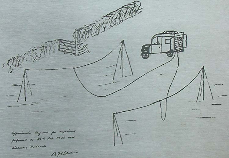
Wikimedia Foundation. 2010.