- Coincidence rangefinder
-
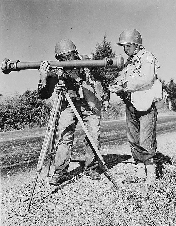
 American soldiers using a coincidence rangefinder with its distinctive single eyepiece during army maneuvers in the 1940s.
 Eyepiece image of a naval rangefinder, showing the displaced image when not yet adjusted for range
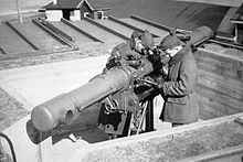 Coincidence range finder
A coincidence rangefinder (stereoscopic rangefinder or parallax rangefinder) is a type of rangefinder that uses mechanical and optical principles to allow an operator to determine the distance to a visible object.
The device consists of a long tube, with two lenses facing forwards at either end, and an operator eye piece in the center. Two prism wedges which when aligned result in no deviation of the light are inserted into the light path of one of the two lenses. By rotating the prisms in opposite directions using a differential gear, a degree of horizontal displacement of the image can be achieved.
Contents
Coincidence rangefinders
The coincidence range finder uses a single eyepiece. Light from the target enters the range finder through two windows located at either end of the instrument. At either side the incident beam is reflected to the center of the optical bar by a pentaprism. The optical bar is ideally made from a material with a low coefficient of thermal expansion so that optical path lengths to not change significantly with temperature. This reflected beam first passes through an objective lens and is then merged with the beam of the opposing side with an ocular prism sub-assembly to form two images of the target which are viewed by the observer through the eyepiece. Since either beam enters the instrument at a slightly different angle the resulting image, if unaltered, will appear blurry. Therefore, in one arm of the instrument a compensator is adjusted by the operator to tilt the beam until the two images match. At this point the images are said to be in coincidence. The degree of rotation of the compensator determines the range to the target by simple triangulation.[1][2] Coincidence rangefinders made by Barr and Stroud used two eyepieces, and may be confused with stereoscopic units. The second eyepiece showed the operator a range scale so that the user could range and read the range scale simultaneously.[3]
Stereoscopic rangefinders
A Stereoscopic range finder uses two eyepieces, and relies on the operators visual cortex to merge the two images into a single picture. A reference mark is separately inserted into each eye piece, the operator first adjusts the direction of the range finder so that the fixed mark is centered on the target, the prisms are then rotated until the mark appears to overlap in the operators combined view.[2][4] Again the range to the target is proportional to the degree of rotation of the prisms.
In November and December 1941, the United States National Defense Research Committee conducted extensive tests between the Bausch and Lomb M1 stereoscopic rangefinder and the Barr and Stroud FQ 25 and UB 7 coincidence rangefinders:
"COINCIDENCE AND STEREOSCOPIC RANGE FINDERS
The first of these reports is concerned with the comparative test of coincidence and stereoscopic range finders. (353) In these tests the American stereoscopic Height Finder Ml was operated against the British coincidence type Range Finders FQ 25 and UB 7, in ranging on fixed ground targets, moving naval targets and moving aerial targets. The coincidence and stereoscopic methods utilize the same basic principles of geometrical optics for the determination of the distance to a target. The two methods differ radically, however, in the nature of the criterion presented for human judgement. These British instruments were of the split field coincident type. American crews were being trained at Fort Monroe to operate the coincidence instruments but this plan was dropped when six British seamen, who were experienced range takers, were made available for the tests. Until recently the British Services had tended strongly to the coincidence type of instrument while the American Services had adopted the stereoscopic principle for long-base instruments at least. The decisions of both the British and American Services apparently grow out of different interpretations of the experience of the Battle of Jutland in World War I and are of no concern in this place.
Tests were run in November and December 1941 using the British seamen on the British instrument and experienced American observers on the Standard M1. Bad weather conditions and various experimental difficulties and mishaps made it impossible to obtain a really satisfactory quantity of data before the tests hall to be terminated. Fixed target reading were made on targets from 2,700 to 14,500 yards. Only five aerial courses could be recorded and these were all level flight courses, at altitudes of 3,000 to 4000 yards and slant range between 4,000 and 12,000 yards Continuous contact was used. Nine courses were obtained on slow moving naval targets at ranges from 4,000 to 12,000 yards. In these latter courses continuous and broken contact were used at different times.
It was found, throughout the tests, that the performances of the various instruments were more nearly alike when measured in external units (Reciprocal range) than when measured in terms of error at the observer's eye, in spite of marked differences in physical dimensions of the instruments. The American MI has a base length of 4.5 yards and used 12 power; FQ 25 with a 6 yard base used 28 power and UB 7, a portable instrument, has 25 power and 3-yard base. The coincidence instruments did not use internal adjusters but were calibrated on targets of known range. In other words. the net performance of the different instruments were essentially comparable although the instruments exhibited varying degrees of efficiency in performance relative to the size. On aerial courses precision errors of the four instruments were about alike when measured in reciprocal-range units. In UOE[5], the FQ 25 had comparatively poor precision, while the UB 7, for three of the five aerial courses, had very small precision errors. The number of aerial courses was too small to yield much information about consistency of observations from one course to the next.
For the naval target courses, one American instrument was not operating. Precision errors of the other three instruments there similar to those on aerial height courses. In reciprocal range units the three instruments had comparable precision. In UOE the FQ 25 was worse and the UB 7 was better than the American M1. Consistency error of the UB 7 was smaller than that of the M1, even when measured in reciprocal range units, while the FQ 25 was similar in consistency to the Ml, again in reciprocals units. On ground targets the same general situation holds. Consistency errors of the four instruments over the 9-day period were the same when measured in reciprocal-range units. Again the UB 7 was better than the stereoscopic instruments in UOE and the FQ 25 was worse. Consistency over the 9 days was not perceptibly worse than daily consistency for any of the instruments. In other words, the readings over the 9 days did not scatter in total more than did readings for a typical day. An analysis or these results leads to the following conclusions. (1) Performance of the coincidence and stereoscopic instruments was about the same when range errors were measured in yards (2) The UB 7 however, with a virtual base length smaller than that of the American stereoscopic instruments was more efficient than the stereoscopic height finders in terms of performance for its size, while the large coincidence instrument, the FQ 25. was less efficient in this sense. This situation held for all types of targets— fixed ground, naval, and aerial. (3) The UB 7 is somewhat better than the American instrument in consistency on naval targets, even when measured in external units.
This report is attached. as supporting data, to a Report to the Services issued by the Fire Control Division of NDRC (20)This points out that the tests indicate no important difference in the precision obtainable from the two types of instrument— coincidence and stereoscopic They do indicate, however, that the difference in performance between large and small instruments is by no means as great as would be anticipated from simple geometrical optics. The report concludes with the belief that stereoscopic and coincidence acuities are about equal. Under favourable conditions existing instruments of the two types perform about equally well, and the choice between them for any given purpose must be based on matters of convenience related to the particular conditions under which they are to be used." [6]
Height Finder
The angle of sight of a rangefinder and the range to the target, can be combined in a simple computer to produce a measurement of altitude. The resulting instrument becomes a combined height-finder/rangefinder and was standard equipment for land and naval based anti-aircraft units.
See also
 Media related to Rangefinders at Wikimedia Commons
- Dazzle camouflage
- Heliometer
- Laser rangefinder
- Periscope
- Stadiametric rangefinding
References
- ^ Yoder, P.R., "Mounting optics in optical instruments", 2nd Ed., Society of Photo-Optical Instrumentation Engineers, USA (2008), p. 239
- ^ a b range finder: Definition and Much More from Answers.com
- ^ The RN Pocket Gunnery Book, paragraph 359.
- ^ CHAPTER-16-F
- ^ UOE = Units of Error, a standard measure of performance based upon the base length and magnification of a rangefinder.
- ^ Rangefinders and Tracking, Summary Technical report of NDRC, Division 7 (Fire Control), volume 2, p17-18. This volume is a US Government report dating from 1947 and is in the Public Domain.
External links
Categories:- Firearm sights
- Armoured fighting vehicle vision and sighting equipment
- Anti-aircraft weapons
- Military computers
- Optics stubs


Wikimedia Foundation. 2010.